

Description
- Model: GE 489-P5-LO-A20
- Brand: GE Multilin
- Series: 489 Generator Management Relay
- Part Type: Drawout digital generator management and protection relay
- Core Function: Combines generator protection, electrical metering, event recording, control functions, and communications in a panel-mounted relay platform.
- Key Specifications: 5 A phase CT inputs; 20–60 VDC / 20–48 VAC control power; 4 × 4–20 mA analog outputs; basic display; drawout construction; RS232/RS485 communications.
Product Introduction
A low-voltage control circuit can be perfectly healthy while the generator protection relay itself remains unavailable. During a replacement, the important issue is not only matching the 489 family number; the P5 / LO / A20 configuration determines the CT input rating, control-power range, and analog-output interface. GE’s ordering documentation confirms that these parameters are factory-selected.
The 489-P5-LO-A20 is a drawout GE Multilin 489 with 5 A phase-current transformer inputs, 20–60 VDC or 20–48 VAC control power at 48–62 Hz, and four 4–20 mA analog outputs. It uses the basic display configuration rather than the larger enhanced display used by E/T variants.
Core Technical Specifications
| Parameter | Value |
|---|---|
| Manufacturer | GE Multilin |
| Exact Model | 489-P5-LO-A20 |
| Alternate Part Number | SR489-P5-LO-A20 |
| Product Family | Multilin 489 |
| Product Type | Generator Management Relay |
| Mechanical Construction | Fully drawout |
| Phase CT Secondary | 5 A |
| Control Power — DC | 20–60 VDC |
| Control Power — AC | 20–48 VAC, 48–62 Hz |
| Analog Outputs | 4 × 4–20 mA |
| Display | Basic display |
| Phase Current Inputs | Three output-side + three neutral-end CT inputs |
| Ground Current Inputs | Dedicated ground-current input arrangements |
| VT Inputs | Wye or delta configurations |
| Digital Inputs | 9 optically isolated inputs |
| Front Communications | RS232 |
| Rear Communications | RS485 communications ports |
| Protocol | Modbus RTU-compatible communications |
| Local Software | 489PC / EnerVista 489 Setup family |
| Firmware Storage | Flash memory |
| Power Consumption | 25 VA typical / 45 VA maximum |
| Control-Power Ride-Through | Approximately 30 ms in published specifications |
| Operating Temperature | -40°C to +60°C |
| Relative Humidity | Up to 90%, non-condensing |
| Enclosure/IP Classification | IP20-X |
| Mounting | Panel or 19-inch rack |
| Shipping Carton | 12 × 11 × 10 in |
| Maximum Shipping Weight | 17 lb / 7.7 kg |
| Country of Manufacture Listed | Canada |
GE documentation specifies the LO supply range, 5 A CT configuration, four scalable 4–20 mA outputs, 25 VA typical / 45 VA maximum power, fully drawout construction, -40°C to +60°C operating temperature, and IP20-X enclosure classification.
Power and Thermal Note
For cabinet calculations, use the documented 45 VA maximum control-power figure rather than the 25 VA typical value. The latter is useful for normal operating estimates; the maximum value is the safer basis for power-supply sizing and enclosure thermal review.
The power supply is particularly configuration-sensitive. The GE manual warns that the applied control voltage must match the installed LO or HI supply range; applying the wrong voltage can damage the relay.
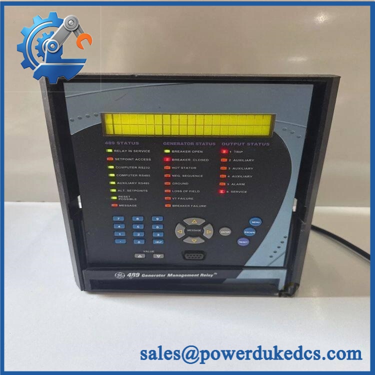
- GE 489-P5-LO-A20
Application Scenarios & Pain Points
During generator startup, a relay replacement can become a protection-engineering issue rather than a simple hardware swap. The 489 monitors phase current, voltage, frequency, real/reactive power, power factor, and other generator parameters, while also providing protective elements such as overcurrent, reverse power, and breaker-related functions.
In utility or industrial generation switchgear, the P5 configuration accepts 5 A phase CT secondaries. A replacement with P1/1 A CT inputs is therefore not electrically equivalent, even when the front panel and basic product family appear identical.
For SCADA integration, the 489 provides serial communications and can communicate with external PLC, DCS, or PC systems. GE’s installation documentation calls for a daisy-chain RS485 arrangement, single-point shield grounding, correct polarity, and 120 Ω termination at the two ends.
In a generator control room exposed to wide seasonal temperatures, the documented operating range extends to -40°C to +60°C. Cabinet temperature still needs to be assessed independently, especially where multiple protection relays are mounted together.
🚨 Common Error Codes & Diagnostic Symptoms
Symptom/Code: Relay fails self-test / internal diagnostic alarm → Diagnosis: The 489 performs internal hardware diagnostics covering processor, memory, analog conversion, and related functions; a persistent self-test failure indicates an internal relay problem after external power and wiring are ruled out. → Action: Remove from service and replace or professionally repair the relay.
Symptom/Code: No metering data from a phase despite verified CT wiring → Diagnosis: A channel-specific analog input or CT interface fault should be considered after confirming the CT secondary circuit and configuration. Because the P5 version expects 5 A CT secondaries, an incorrect CT rating or open circuit can also produce invalid measurements. → Action: Verify CT circuit safety and scaling, then replace the relay if the internal input channel is confirmed defective.
Symptom/Code: RS485 communication loss while local relay functions remain normal → Diagnosis: Check polarity, cable topology, shield grounding, node configuration, and 120 Ω termination before assuming a processor failure. GE specifically requires a daisy-chain arrangement rather than star or stub wiring. → Action: Correct the RS485 network first; replace the relay only after the communications interface is isolated as the failed component.
🚨 Cross-Reference & Lifecycle Migration
The 489-P5-LO-A20 has a precise factory ordering structure:
- P5 = 5 A phase CT secondaries.
- LO = 20–60 VDC or 20–48 VAC control power.
- A20 = four 4–20 mA analog outputs.
- The absence of
E,T, orHindicates that this supplied code is the basic-display, non-enhanced, standard-environment configuration rather than an enhanced-display or Ethernet/harsh-environment variant. GE’s ordering table documents these distinctions.
The 489 family uses a drawout unit plus companion fixed case. The case normally remains wired in place, while the relay can be removed for maintenance; the case incorporates the automatic CT shorting arrangement needed for safe withdrawal when correctly installed.
There is no simple “previous revision equals direct replacement” statement that should be applied to every 489 variant. Instead, verify P1/P5 CT rating, LO/HI control power, analog-output configuration, display version, and any enhanced/Ethernet/harsh-environment options against the existing relay.
Firmware: Firmware is stored in flash memory, and the front RS232 port supports firmware upgrades. GE documentation also states that the 489PC software is supplied with the unit.
A replacement relay should therefore be matched to the plant’s software and firmware baseline. Do not assume that a newer firmware image is automatically suitable for an older protection application; preserve the approved settings and verify the replacement before energizing the generator protection system.
Lifecycle status: The 489 is a legacy/discontinued generation-management platform, but current specialist suppliers continue to list new-surplus, repaired, and used units.
For buffer-stock planning, store the complete ordering code and firmware revision. A generic 489 unit does not provide enough information to guarantee interchangeability.
Field Engineer’s Tech Notes
Warning 1 — Respect the automatic CT shorting mechanism, but verify it mechanically.
The 489 is a drawout relay, and GE specifies an automatic CT-short arrangement through the fixed case. Never assume the mechanism is functioning merely because the relay slides out normally. Inspect the case contacts and follow the approved withdrawal procedure (CT secondary safety takes priority).
Warning 2 — Match LO power before connecting anything.
For this model, the correct control-power range is 20–60 VDC or 20–48 VAC at 48–62 Hz. Do not connect a 125 VDC or 120 VAC source because another GE 489 in the same plant uses an HI supply. The GE manual explicitly warns that an incorrect supply range can damage the unit.
Strict QA & Testing SOP
Step 1 — Identity and configuration inspection
Record the exact nameplate code 489-P5-LO-A20, serial number, manufacturing information, firmware revision, CT rating, control-power range, and analog-output designation.
Step 2 — Drawout mechanical inspection
Check the relay faceplate, basic LCD, keypad, extraction mechanism, rear connectors, terminal hardware, and mating case for corrosion, bent contacts, cracked plastics, or previous repair evidence.
Step 3 — Case compatibility verification
Inspect the companion SR489 case. GE documents the relay and case as separate mechanical pieces, so the receiving case must support the exact drawout relay configuration.
Step 4 — Control-power test
Apply a protected supply within the LO range: 20–60 VDC or 20–48 VAC. Confirm startup, display initialization, and absence of internal self-test alarms.
Step 5 — Front-panel test
Verify the LCD and keypad operation. Confirm access to Actual Values, Setpoints, target messages, and relay information screens.
Step 6 — CT input simulation
Using an approved relay test set, inject controlled 5 A-equivalent CT signals and verify phase-current measurement accuracy and scaling. Never open an energized CT secondary.
Step 7 — VT input and metering test
Apply controlled voltage inputs and verify voltage, frequency, power, power factor, MW, Mvar, and related metering values.
Step 8 — Analog-output verification
Test all four 4–20 mA outputs using calibrated measurement equipment. Confirm output scaling against the configured source parameters.
Step 9 — Protection-function testing
Run approved secondary-injection tests for relevant overcurrent, negative-sequence, reverse-power, breaker-related, and other enabled functions. Record pickup and timing results.
Step 10 — Communications verification
Test front RS232 service access and rear RS485 communications. Confirm correct polarity, addressing, protocol behavior, and termination.
Step 11 — Firmware/configuration capture
Record the installed firmware revision and save the relay configuration/setpoint file where permitted.
Step 12 — Final preservation and packing
After testing, protect the relay in ESD-safe packaging, cushion the drawout mechanism, prevent connector impact, and record final QA status.
Test videos are available for qualifying inventory when pre-shipment inspection evidence is required.
Buyer’s FAQ
Q1. Can the 489-P5-LO-A20 be hot-swapped?
It is a drawout relay, but that does not mean unrestricted live withdrawal is acceptable. GE’s installation documentation specifically warns that control power must be handled correctly, while the case provides automatic CT shorting for the CT circuits. Follow the site’s approved switching procedure and GE withdrawal procedure before removing the relay.
Q2. How do I verify a New Original unit before receiving it?
Request photographs of the complete model label, serial number, front display, rear connector area, and drawout mechanism. The order code must show P5-LO-A20 rather than merely “489.” A supplier record for the exact model identifies the P5 CT input, LO control power, A20 analog outputs, and basic display.
For audit-sensitive purchasing, also record the unit’s firmware revision and country-of-manufacture evidence.
Q3. What warranty should be specified?
Warranty is supplier- and condition-dependent for this legacy relay. Current secondary-market suppliers advertise different coverage periods depending on whether the unit is repaired, surplus, or previously used. Those terms should be written directly into the purchase order rather than assumed from the GE model number.
Specify condition, test status, warranty duration, and return procedure for the exact unit being purchased.
Q4. Does the relay come with the latest firmware pre-loaded?
Not necessarily. The 489 uses flash memory for firmware upgrades, and the front RS232 port supports firmware updates.
For a plant replacement, ask the supplier to report the installed firmware revision before shipment. The correct replacement is the one compatible with the approved application and configuration—not simply the one carrying the newest software revision.
Lifecycle & Asset-Control Note
The GE Multilin 489-P5-LO-A20 is a legacy 5 A / low-voltage / 4–20 mA / basic-display generator-management configuration. Current specialist listings continue to show availability, but the platform should be managed as a legacy spare with configuration-specific procurement controls.
For warehouse records, retain 489-P5-LO-A20, SR489-P5-LO-A20 cross-reference, serial number, firmware revision, CT rating, control-pwer range, analog-output configuration, case compatibility, COO, certification evidence, and QA test record as separate fields.











 Start Chat


