

Description
- Model: GE 531X121PCRALG1
- Brand: GE / General Electric
- Series: 531X Boards / DC300 Drive
- Part Type: Power Connection Board / Power Connect Card
- Core Function: Interfaces and distributes power within the GE DC300 drive’s SVSF1 four-quadrant (4Q) power-conversion architecture. Current parts references consistently identify the exact board as a DC300 SVSF1 4Q Power Connection Board/Card.
- Key Specs: G1 variant; 190–500 V drive-voltage range reported by specialist documentation; approximately 27.8 × 21.2 × 2.5 cm and 0.58 kg in one current inventory record.
Product Introduction
The GE 531X121PCRALG1 is installed as a board-level power-connection interface within the DC300 drive family, specifically identified in legacy parts references as the SVSF1 4Q power connection card. It is not a PLC CPU, analog input card, or general-purpose communications board. Its role is tied to the internal power architecture of the drive, so correct application matching starts with the drive model and power-stage configuration.
For the G1 version, one specialist source reports compatibility with a 190–500 V range. That figure should be treated as a drive-application value, not a simple standalone board supply rating. A board sold under the same family can have different application suffixes, and other 531X power-connection cards are associated with different DC300, DC1000, or AC300 equipment.
Core Technical Specifications
| Parameter | Value |
|---|---|
| Manufacturer | GE / General Electric |
| Exact Part Number | 531X121PCRALG1 |
| Series | 531X Boards |
| Product Family | GE DC300 Drive |
| Board Type | Power Connection Board / Power Connect Card |
| Functional Designation | SVSF1 4Q Power Connection |
| Drive Architecture | four-quadrant power-conversion system |
| Variant | G1 |
| Reported Compatible Drive Voltage | 190–500 V |
| Approx. Board Dimensions | 278 × 212 × 25 mm |
| Approx. Unit Weight | 0.58 kg |
| Electrical Role | Power connection/interface within drive |
| Firmware | None as a standalone software-configurable module |
| Installation | Internal drive cabinet / board assembly |
| Cooling | Dependent on host-drive airflow and cabinet design |
| Standalone Operating Temperature | Exact OEM value not reliably established |
| Standalone Storage Temperature | Exact OEM value not reliably established |
| Certifications | Exact board-level approval not reliably established from the reviewed sources |
| Related Part Family | 531X power/interface boards |
The 27.8 × 21.2 × 2.5 cm / 0.58 kg figures come from a current supplier record. A separate specialist source confirms the board type and identifies the 190–500 V application range for the G1 version. These should be used as procurement references rather than certified mechanical or electrical design values.
Power and Thermal Note
Do not assign a generic wattage to the 531X121PCRALG1. This is a power-connection board inside a high-energy drive, and its thermal behavior depends on the host drive, power flow, switching conditions, and cabinet airflow. One third-party record lists a broad input-power description, but that information is not sufficiently authoritative to use as an engineering design limit.
The specialist reference also warns that the drive remains an electrically hazardous system after disconnecting incoming power because stored energy can remain in the drive circuitry.
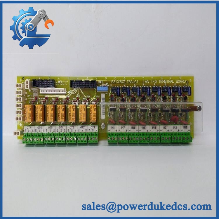
GE 531X121PCRALG1
Application Scenarios & Pain Points
A drive stops operating after a power-stage event, while the control electronics still appear responsive. In this situation, the power-connection card becomes one of the boards worth inspecting, particularly when the drive’s own diagnostic tools identify a hardware problem in the power path. A specialist repair reference specifically describes using the drive’s diagnostic facility to determine failed or deteriorating components before replacing the power-connection board.
On industrial DC motor systems, the SVSF1 designation identifies the board with the four-quadrant power-conversion architecture. Four-quadrant drive arrangements are used where controlled motor operation is required in both directions and regenerative operation is part of the process.
In material-handling machinery, a failed power-interface board can result in loss of drive enable, abnormal power-stage behavior, or an inability to complete the drive’s startup sequence. The actual symptom depends on which part of the drive’s internal power path has been affected.
For large legacy drive cabinets, mechanical and environmental conditions deserve attention. A 50°C+ cabinet ambient leaves little room for assumptions about board life or cooling, especially where the drive uses forced ventilation and multiple power-stage components are operating together.
During maintenance of an older installation, exact board identity matters because the 531X family contains numerous visually similar power and interface cards. Current GE parts lists show 531X121PCRALG1, 531X121PCRALG2, 531X121PCRALG5, and other 531X121 variants with different descriptions.
🚨 Common Error Codes & Diagnostic Symptoms
Because the 531X121PCRALG1 is a board-level drive component rather than an independent intelligent controller, there is no reliable standalone error-code table attributable exclusively to the board. Drive diagnostics should be interpreted at the system level.
Symptom/Code: diagnostic identifies a power-stage or power-connection hardware fault → Diagnosis: The drive’s internal diagnostic tools can identify failed or deteriorating components; a persistent hardware indication after external power and wiring checks makes the power-connection assembly a candidate. → Action: De-energize the drive, discharge stored energy, inspect the board and associated power connections, then replace the board if confirmed defective.
Symptom/Code: Drive fails to start after replacement of an upstream power-stage component → Diagnosis: Incorrect board variant, wrong jumper/configuration condition, damaged connector, or an unresolved power-stage fault can all prevent normal startup. → Action: Verify the exact 531X catalog number and the complete drive configuration before replacing additional boards.
Symptom/Code: Intermittent drive power behavior / repeated hardware diagnostic events → Diagnosis: Loose connectors, oxidized contacts, thermal stress, damaged PCB traces, or an aging component on the power-connection card can produce intermittent faults. → Action: Inspect the card, connectors, and mating hardware under ESD-controlled conditions; replace the board after confirming the fault path.
🚨 Cross-Reference & Lifecycle Migration
The most important cross-reference is within the 531X121 power-connection family. Current legacy parts lists identify:
- 531X121PCRALG1 — SVSF1 4Q Power Connection.
- 531X121PCRALG2 — Power Connection Card.
- 531X121PCRALG5 — 4Q Power Connection.
- Other 531X121PCRA variants exist with different suffixes and applications.
Do not interpret those family similarities as proof of direct substitution. The suffix can identify a different drive-voltage or hardware application.
A current specialist reference specifically describes the G1 version as compatible with 190–500 V. That makes the host-drive voltage a mandatory receiving check.
Firmware: No standalone firmware-flashing procedure has been established for the 531X121PCRALG1. Unlike a modern intelligent drive controller, this is a board-level power-interface assembly. Compatibility therefore depends on hardware version, drive topology, connection arrangement, and application voltage, not a field firmware image.
Lifecycle status: The 531X121PCRALG1 belongs to a legacy drive platform. Current specialist sources still list the exact board, including new-surplus and repair/replacement channels, while industrial parts catalogs classify it as old-generation equipment.
For buffer-stock planning, record the complete 531X121PCRALG1 suffix, host-drive model, voltage class, board revision, and test status. Keeping only “531X power connection board” in the ERP is inadequate.
Field Engineer’s Tech Notes
Warning 1 — Treat this as a high-energy drive component.
GE service documentation warns that hazardous electrical energy can remain after incoming power has been disconnected. Allow the prescribed discharge interval and verify the DC bus is safe before touching the board (this is not a routine low-voltage PCB swap).
Warning 2 — Verify the drive voltage before installing a G1 card.
The G1 variant is reported for the 190–500 V application range. Do not use that figure as permission to install the board in another 531X/ configuration simply because the connector pattern looks similar. Match the drive nameplate, schematic, and original board marking first.
Strict QA & Testing SOP
Step 1 — Part identity inspection
Confirm 531X121PCRALG1, board revision, visible GE markings, and any secondary identification. Photograph the label before removing the board from ESD packaging.
Step 2 — Physical inspection
Inspect the PCB for cracked solder joints, damaged traces, discoloration, overheated components, corrosion, bent connectors, and signs of unauthorized rework.
Step 3 — Connector inspection
Check every board-to-drive connector for oxidation, deformation, contamination, and loose retaining hardware. Do not rely on continuity alone; mechanical contact quality matters.
Step 4 — Voltage-application verification
Confirm that the intended host drive falls within the application associated with the G1 version. The available specialist reference reports 190–500 V.
Step 5 — Static and insulation checks
Under an approved laboratory procedure, perform appropriate resistance and insulation checks on the relevant power paths. Do not apply arbitrary high-voltage testing to semiconductor-connected circuits without the manufacturer’s approved procedure.
Step 6 — Drive-level functional test
Install the board in the correct test drive and perform the diagnostic sequence. The specialist repair reference specifically recommends using the drive’s built-in diagnostic tools to identify hardware issues.
Step 7 — Power-stage monitoring
With the drive operating under a controlled test load, monitor DC bus behavior, drive status, alarms, and abnormal heating. Compare results against the applicable drive service documentation.
Step 8 — Thermal inspection
Use calibrated temperature measurement to look for abnormal hot spots around power-connect circuitry, connectors, and adjacent components. Test duration should be long enough to reveal thermal behavior under the intended load.
Step 9 — Final documentation
Record part number, revision, host-drive model, voltage class, test conditions, diagnostic results, photographs, and final disposition.
Step 10 — Packaging
After passing inspection, return the board to ESD shielding packaging with rigid edge protection. Keep heavy objects away from the PCB surface.
Test videos are available for qualifying inventory when pre-shipment evidence is required.
Buyer’s FAQ
Q1. Can I hot-swap the 531X121PCRALG1?
No routine hot-swap procedure should be assumed. This is a power-interface board inside a high-energy drive, and the drive can retain hazardous stored energy after incoming power is removed. Follow the site lockout/tagout process and the applicable GE service procedure before board removal.
Q2. How do I verify a New Original board?
Check the complete 531X121PCRALG1 marking, board revision, physical PCB layout, connectors, and original packaging. Ask for photographs of the actual board rather than accepting a generic 531X catalog image.
For an audit-controlled purchase, retain serial/identification records where present and document whether the item is New Original, New Surplus, repaired, or refurbished.
Q3. What warranty should I specify?
Warranty depends on the supplier and inventory condition. Current specialist listings advertise repair and replacement support, while some aftermarket suppliers publish their own fixed warranty periods.
Put the warranty period and condition directly into the purchase order. Avoid treating an aftermarket warranty as a GE factory warranty.
Q4. Does this board require firmware to be loaded?
No conventional field firmware package has been established for the 531X121PCRALG1. It is a board-level power-connection component, so the critical compatibility variables are board suffix, revision, host-drive configuration, voltage range, and physical interface.
Lifecycle & Asset-Control Note
GE 531X121PCRALG1 is a legacy four-quadrant power-connection board. Current industrial records continue to identify the exact part, while legacy catalogs show several closely related 531X121 power-connection variants.
For critical installations, maintain revision-controlled spare stock and record the host-drive voltage class. The available specialist data identifies the G1 version with a 190–500 V application range, so that parameter should be checked before a replacement is released from the warehouse.











 Start Chat


