

Description
- Model: 531X304IBDAMG1
- Brand: GE / General Electric
- Series: 531X
- Part Type: AC2000 Base Drive Card
- Core Function: Provides the base-drive circuitry used within the GE AC2000 drive power-control architecture.
- Key Specs: G1 hardware variant; populated PCB assembly with multiple driver sections, semiconductor devices, jumper positions, crystal oscillators, LEDs, and board-level terminal/connector interfaces.
- Lifecycle: Legacy / obsolete hardware with specialist aftermarket and repair availability.
Product Introduction
The GE 531X304IBDAMG1 is installed inside the GE AC2000 drive architecture as an AC2000 Base Drive Card. It is a board-level power-control assembly, not a standalone PLC I/O module or communications processor. Specialist parts references consistently assign this exact catalog number to the AC2000 base-drive function.
Physically, the board is described as having three similar sections, with semiconductor devices, resistors, capacitors, integrated circuits, jumper pins, transistors, crystal oscillators, LEDs, metal brackets, and male terminal connection points. That construction makes revision control important during legacy migration or drive refurbishment (a similar-looking 531X board should not be released from stock without checking the complete suffix).
Core Technical Specifications
| Parameter | Value |
|---|---|
| Manufacturer | GE / General Electric |
| Exact Part Number | 531X304IBDAMG1 |
| Series | 531X Boards |
| Product Family | GE AC2000 |
| Board Type | Base Drive Card |
| Functional Designation | Base Driver / Base Drive Card |
| Hardware Variant | G1 |
| Board Architecture | 3 primary sections reported |
| Semiconductor Components | Transistors, diodes, integrated circuits |
| Passive Components | Resistors, resistor networks, capacitors |
| Timing Components | Crystal oscillators |
| Configuration Features | Multiple jumper positions |
| Status Indication | Multiple red LEDs |
| Electrical Interface | Male terminal connection points and board connectors |
| Firmware | No standalone field firmware package identified |
| Host Equipment | GE drive systems |
| Operating Temperature | Exact board-specific OEM value not verified |
| Storage Temperature | Exact board-specific OEM value not verified |
| Power Consumption | Exact standalone board value not verified |
| Heat Dissipation | Exact standalone board value not verified |
| Mounting | Internal drive assembly |
| Cooling | Dependent on host-drive airflow and enclosure design |
| Lifecycle | Obsolete / legacy |
The exact part number and base-drive designation are supported by several independent industrial parts records. Current inventory catalogs also list other 531X304 variants, confirming that this is a family of closely related but separately identified boards.
Power and Thermal Note
No dependable OEM figure was located for the standalone power consumption or heat dissipation of 531X304IBDAMG1. Do not insert an estimated wattage into an approved cabinet thermal calculation.
For engineering work, calculate loading from the complete drive assembly and its operating condition. The board’s thermal behavior is affected by the surrounding power electronics, cabinet ventilation, switching activity, and ambient temperature.
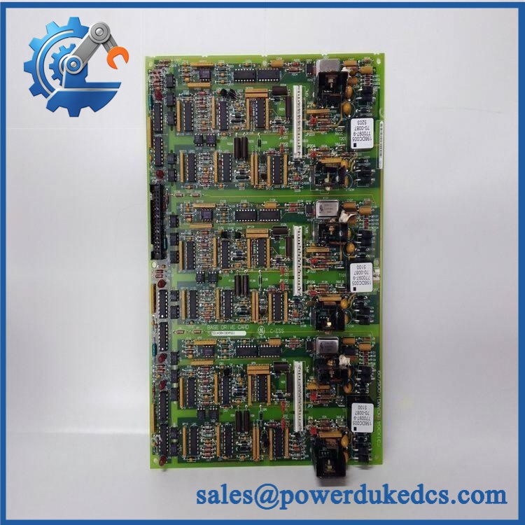
GE 531X304IBDAMG1
Application Scenarios & Pain Points
A production line’s drive develops a persistent drive-stage fault following years of operation. Once incoming power, field wiring, and other external causes have been eliminated, the base-drive board becomes one of the assemblies requiring inspection. The exact 531X304IBDAMG1 is documented as an base-drive card.
For legacy motor-drive cabinets, this board forms part of the internal interface between drive-control circuitry and the power stage. A failure within the driver path can prevent normal switching behavior even when upstream control commands remain present.
During refurbishment projects, revision control is essential because several 531X304 variants share the same general description. Current listings include IBDAMG1 alongside IBDAGG1, IBDAHG1, IBDALG1, IBDANG1, IBDARG1, and IBDASG1. The catalog suffix must therefore be retained rather than reduced to “531X304 base drive.”
In high-temperature drive rooms, inspect ventilation before blaming the circuit board. A 50°C+ cabinet ambient can accelerate degradation of capacitors, semiconductor junctions, solder joints, and connectors, particularly when the original cooling system is dirty or partially obstructed.
🚨 Common Error Codes & Diagnostic Symptoms
The 531X304IBDAMG1 does not have an independent software error-code table. Fault information normally originates from the host drive rather than the PCB itself.
Symptom/Code: Drive reports a persistent base-drive or power-stage fault → Diagnosis: A failed driver circuit, damaged semiconductor path, connector problem, or an associated power-stage fault can prevent correct drive operation. The board should not be condemned until external causes are checked. → Action: Follow the diagnostic procedure, isolate the failed assembly, and replace the board when confirmed defective.
Symptom/Code: Drive trips repeatedly after warming up → Diagnosis: Temperature-dependent failure can result from aging components, cracked solder joints, marginal connectors, or semiconductor degradation. → Action: Compare cold and stabilized-temperature behavior and inspect the board for localized heating before approving replacement.
Symptom/Code: Abnormal or missing LED indication on the board → Diagnosis: An abnormal LED pattern can reflect a local supply problem, board-level driver failure, or a fault elsewhere in the drive that prevents the board from reaching its normal operating state. → Action: Interpret the LED condition using the applicable documentation rather than assigning a generic fault code.
🚨 Cross-Reference & Lifecycle Migration
The 531X304 family contains numerous related base-drive assemblies. Current parts records include:
- 531X304IBDAGG1 — Base Drive Card
- 531X304IBDAHG1 — Base Drive Card
- 531X304IBDAJG1 — Base Drive Card
- 531X304IBDALG1 — Base Drive Card
- 531X304IBDAMG1 — Base Drive Card
- 531X304IBDANG1 — Base Drive Card
- 531X304IBDARG1 — Base Drive Card
- 531X304IBDASG1 — Base Drive Card
These are family references, not confirmed drop-in equivalents. No reliable source located here establishes that another 531X304 suffix is a direct replacement for IBDAMG1. The host drive model, PCB revision, connector layout, jumper configuration, and application must be checked.
Firmware: No independent field firmware process was identified for this board. It is a hardware base-drive assembly; its interchangeability is principally determined by the drive architecture and board configuration.
Lifecycle status: Obsolete / legacy. The exact IBDAMG1 remains listed in specialist industrial inventories, including repair and surplus channels. Historical industrial-control inventories also document IBDAMG1 as a stocked Base Drive Card.
For buffer stock, keep the full suffix, board revision, host-drive model, and jumper configuration in the asset record. A generic 531X304 entry is not enough.
Field Engineer’s Tech Notes
Warning 1 — Photograph the jumper configuration before removal.
This board contains multiple jumper positions. Do not assume the replacement should have a visually convenient default arrangement. Compare the original board with the approved schematic and record every jumper position first (a one-position difference can alter the board’s intended operation).
Warning 2 — Treat the board as part of a high-energy drive.
Never begin removal immediately after opening the upstream disconnect. Follow the discharge procedure and verify that stored DC energy has reached a safe level before touching the PCB, connectors, or associated power circuitry.
Strict QA & Testing SOP
Step 1 — Inbound identity check
Confirm 531X304IBDAMG1, visible GE markings, board revision, and any secondary assembly number. Photograph the exact identification.
Step 2 — Physical inspection
Inspect both sides of the PCB for burned areas, discoloration, cracked solder joints, lifted traces, corrosion, damaged components, or evidence of prior repair.
Step 3 — Jumper documentation
Record every jumper location before testing. Compare the configuration with the original installation record or approved engineering drawing.
Step 4 — Connector inspection
Examine male terminals and mating connectors for oxidation, bent contacts, damaged retention hardware, contamination, or looseness.
Step 5 — Component screening
Under an approved bench procedure, check relevant diodes, transistors, capacitors, resistors, and semiconductor junctions. Avoid arbitrary high-voltage tests across semiconductor-connected circuits.
Step 6 — ESD-controlled installation
Install the board into a compatible test assembly using grounded ESD procedures.
Step 7 — Power-up verification
Apply power through a properly protected test arrangement and monitor startup behavior. Check for abnormal LED patterns, unexpected current draw, and immediate drive faults.
Step 8 — Drive diagnostic test
Run the host diagnostic sequence and compare the resulting status against a known-good board where available.
Step 9 — Functional operation
Operate the drive under controlled conditions and, where appropriate, representative load. Monitor drive status, fault behavior, and control response.
Step 10 — Thermal inspection
Monitor the board and surrounding drive cabinet for abnormal hot spots during the test period. Pay particular attention to semiconductor and connector areas.
Step 11 — Test record
Document the board identity, revision, jumper settings, test-drive model, test conditions, fault observations, and final disposition.
Step 12 — Preservation and packing
After acceptance, place the board in an ESD shielding bag with rigid edge protection. Prevent pressure on components and connector areas during transport.
Test videos are available for qualifying inventory when pre-shipment inspection evidence is required.
Buyer’s FAQ
Q1. Can the 531X304IBDAMG1 be hot-swapped?
Do not assume live removal is permitted. This is an internal drive base-drive board, and hazardous stored energy can remain after the incoming supply has been disconnected.
Use the plant’s lockout/tagout procedure, follow the drive discharge requirements, and verify the DC bus is safe before accessing the board.
Q2. How do I verify a New Original unit?
Request photographs of the actual PCB, including the complete 531X304IBDAMG1 marking, revision, jumper area, LEDs, connectors, and overall board layout.
For a New Original claim, also request original packaging and traceability information where available. A generic photograph of another 531X304 variant does not establish exact part identity.
Q3. What warranty should be specified?
Warranty depends on the supplier and condition of the inventory. Current specialist records show warranty-backed sales and repair services for this exact part, including a published three-year supplier warranty from one source. This is a supplier-specific commercial term, not a universal GE factory warranty.
The purchase order should state the condition—New Original, New Surplus, repaired, or refurbished—together with the warranty period.
Q4. Does this board require firmware to be loaded?
No standalone firmware-loading procedure was established for the 531X304IBDAMG1. This is a board-level drive component, so compatibility is primarily controlled by the exact hardware variant, revision, jumper arrangement, and host drive configuration.
Lifecycle & Asset-Control Note
The GE 531X304IBDAMG1 is documented as an Base Drive Card within the 531X family and is treated as obsolete/legacy hardware by specialist suppliers, although secondary inventory and repair channels remain available.
For critical installations, maintain revision-controlled stock and record the complete part number, board revision, jumper configuration, host-drive model, physical condition, COO, certification evidence, and QA status. Do not release another 531X304 suffix as an IBDAMG1 substitute without documented compatibility confirmation.











 Start Chat


