

Description
- Model: GE 531X304IBDAMG1
- Brand: GE / General Electric
- Series: 531X Boards / AC2000 Drive
- Part Type: AC2000 Base Drive Card / IBD Base Driver Board
- Core Function: Provides base-drive circuitry within the GE AC2000 drive architecture, handling drive-stage control and associated interface functions.
- Key Specifications: Three major board sections; multiple jumpers, transistors, diodes, capacitors, integrated circuits, crystal oscillators, LEDs, and male terminal connection points. Specialist references identify the exact part as an AC2000 Base Drive Card.
- Lifecycle: Legacy/obsolete component, with current secondary-market availability and repair support.
Product Introduction
The GE 531X304IBDAMG1 is installed within the AC2000 drive power-control architecture as an IBD base-drive board. GE 531X records consistently identify this exact catalog number as an AC2000 Base Drive Card, while related 531X304 boards carry similar base-driver functions for other equipment configurations.
Physically, the board is a populated circuit assembly rather than a standalone programmable controller. Available technical descriptions identify three similar board sections containing semiconductor devices, capacitors, resistors, jumpers, integrated circuits, crystal oscillators, LEDs, and connector pins. The G1 suffix must be retained in the warehouse record because the 531X304 family contains numerous different suffixes that are not automatically interchangeable (a visually similar board can still have a different drive application).
Core Technical Specifications
| Parameter | Value |
|---|---|
| Manufacturer | GE / General Electric |
| Exact Part Number | 531X304IBDAMG1 |
| Series | 531X Boards |
| Product Family | Drive |
| Board Designation | IBD |
| Product Type | Base Drive Card |
| Functional Description | Base driver / base drive circuit board |
| Board Construction | Multi-section populated PCB |
| Major Board Sections | 3 |
| Semiconductor Devices | Transistors, diodes, integrated circuits |
| Passive Components | Resistors, resistor networks, capacitors |
| Timing Components | Crystal oscillators |
| Configuration Hardware | Jumper pins |
| Status Indication | Multiple red LEDs |
| Electrical Interface | Male terminal connection points and board connectors |
| Firmware | No standalone field firmware package established |
| Host Equipment | GE drive systems |
| Approx. Dimensions | Exact OEM dimensional specification not reliably established |
| Approx. Weight | Exact OEM net weight not reliably established |
| Power Consumption | Exact board-level value not reliably established |
| Operating Temperature | Exact board-level value not reliably established |
| Storage Temperature | Exact board-level value not reliably established |
| Cooling | Dependent on host drive and cabinet airflow |
| Mounting | Internal drive board assembly |
| Lifecycle | Legacy / obsolete |
The Base Drive Card designation is directly supported by current industrial parts records, while the detailed component description is supported by specialist technical references.
Power and Thermal Note
A reliable OEM figure for the 531X304IBDAMG1’s independent power consumption or heat dissipation was not located. Do not substitute a generic 531X drive-board wattage into a cabinet thermal calculation.
Because this card operates inside a drive power-control assembly, thermal loading is influenced by the complete drive, semiconductor switching losses, airflow, and operating load. Use the applicable drive documentation and measured cabinet conditions for engineering calculations.
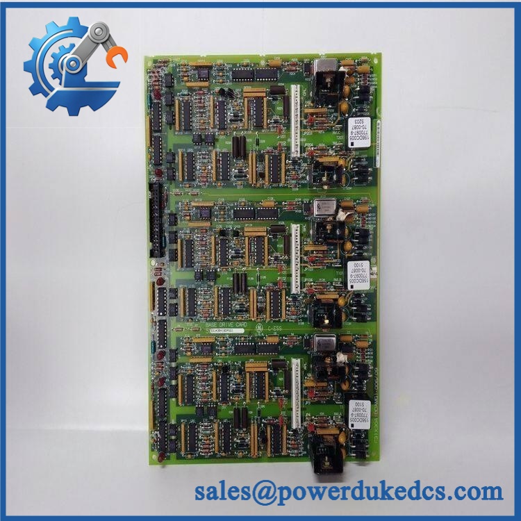
GE 531X304IBDAMG1
Application Scenarios & Pain Points
A legacy drive develops an intermittent drive-stage fault after years of operation. When external wiring and the main control logic have been eliminated as causes, the base-drive assembly becomes an important inspection point. Specialist references describe the 531X304IBDAMG1 specifically as the base-drive card.
In industrial motor-drive applications, the board’s semiconductor and timing circuitry participates in the internal drive-control chain. Failure of an associated driver stage can prevent correct operation even when upstream command signals appear normal.
For maintenance teams supporting old installations, board-level interchangeability is a recurring problem. Current 531X records contain many 531X304 variants, including IBDAHG1, IBDALG1, IBDANG1, IBDARG1, and IBDASG1, all described as related base-drive cards but not established as universal substitutes.
At elevated cabinet temperatures, semiconductor aging becomes more significant. A 50°C+ cabinet ambient should trigger a review of fan operation, filter condition, and airflow before attributing every intermittent fault to the PCB itself.
🚨 Common Error Codes & Diagnostic Symptoms
Because the 531X304IBDAMG1 is a board-level drive component, GE documentation does not establish a universal standalone error-code list for the PCB. Diagnostic evidence must be interpreted through the host drive.
Symptom/Code: Drive-level base-drive or firing-circuit fault indication → Diagnosis: A persistent power-stage drive fault can indicate a failed driver component, damaged gate-drive path, connector problem, or another associated power-stage fault. The board should only be condemned after the surrounding circuitry is checked. → Action: De-energize the drive, inspect the base-drive board and associated interfaces, then replace the board if testing confirms it as the failed assembly.
Symptom/Code: Drive intermittently trips after warm-up → Diagnosis: Thermal stress, aging semiconductor components, deteriorated solder joints, or connector resistance can cause a fault that appears only after the assembly reaches operating temperature. → Action: Compare cold and hot test behavior, inspect for localized heating, and replace the board when the fault follows the card.
Symptom/Code: Multiple red LEDs show abnormal or missing indication → Diagnosis: The board contains multiple status LEDs, and an abnormal pattern can indicate loss of a local supply, driver-stage malfunction, or a fault elsewhere in the drive that prevents normal board operation. → Action: Use the exact diagnostic procedure to interpret the LED state; replace the card only after external causes are eliminated.
🚨 Cross-Reference & Lifecycle Migration
The 531X304IBDAMG1 belongs to a broad family of GE base-drive cards. Current legacy inventories identify several nearby variants:
- 531X304IBDAGG1 — Base Drive Card
- 531X304IBDAHG1 — Base Drive Card
- 531X304IBDALG1 — Base Drive Card
- 531X304IBDANG1 — Base Drive Board / -related variant
- 531X304IBDARG1 — Base Drive Card
- 531X304IBDASG1 — Base Driver Card
- 531X304IBDAMG1 — Base Drive Card
These should be treated as related family members, not confirmed direct replacements. No reliable source located during this verification establishes a universal drop-in replacement from one suffix to another.
The G1 board is associated with the older drive architecture. There is no modern firmware migration process associated with this PCB itself; compatibility is primarily hardware- and application-dependent.
Firmware: No standalone firmware-flashing requirement was established for the 531X304IBDAMG1. The relevant variables are board revision, drive architecture, connector arrangement, jumper configuration, and the specific cabinet design.
Lifecycle status: Current industrial records classify the exact 531X304IBDAMG1 as obsolete/discontinued, although specialist suppliers continue to list it for sale and repair.
For buffer stock, keep at least one application-verified spare where this card is tied to a production-critical drive. Do not substitute another 531X304 suffix without a documented compatibility check.
Field Engineer’s Tech Notes
Warning 1 — Never move the jumpers casually.
The board contains multiple jumper positions, and these may determine operating or interface conditions. Photograph every jumper position before removing the original card. Do not assume a factory-looking jumper pattern is universal across 531X304 variants (the suffix matters).
Warning 2 — Discharge the drive before touching the PCB.
This is an internal drive power-control board, not a low-voltage PLC card. Disconnect incoming power, follow the discharge procedure, and verify stored DC voltage is at a safe level before removing connectors or the board. A powered or incompletely discharged drive can expose technicians to hazardous energy.
Strict QA & Testing SOP
Step 1 — Identity inspection
Confirm 531X304IBDAMG1, all visible board markings, assembly numbers, and revision information. Photograph the PCB before unpacking.
Step 2 — Physical inspection
Check the PCB, mounting brackets, connector pins, jumper headers, LED assemblies, solder joints, and component bodies for cracks, discoloration, corrosion, or previous repair work.
Step 3 — Jumper verification
Compare every jumper position with the original board or approved drawing. Record the configuration before changing anything.
Step 4 — Connector inspection
Check male terminal points and mating connectors for oxidation, bent pins, loose hardware, and contamination. Connector condition can mimic an electronic board failure.
Step 5 — Static and insulation checks
Under an approved laboratory procedure, perform suitable resistance and insulation checks. Do not apply arbitrary megohmmeter or high-potential tests directly across semiconductor circuits.
Step 6 — Bench component screening
Where technically appropriate, check suspect diodes, transistor junctions, resistor networks, capacitors, and visible semiconductor paths against the approved repair/test procedure.
Step 7 — Drive-rig installation
Install the board into a compatible test assembly. Confirm the exact host-drive configuration before energization.
Step 8 — Diagnostic test
Run the drive’s approved diagnostic sequence and monitor the board’s LED behavior, control signals, and drive fault status.
Step 9 — Functional load test
Where a suitable test stand exists, operate the drive under controlled load and monitor drive-stage behavior and abnormal temperature rise. Compare the card against a known-good reference where available.
Step 10 — Thermal observation
Check for localized heating around driver components, connectors, and power-interface areas during the controlled test. A hot spot that follows the replacement card is useful diagnostic evidence.
Step 11 — Final documentation
Record part number, board revision, jumper configuration, test-drive model, diagnostic results, test duration, and final disposition.
Step 12 — Packaging
After acceptance, place the board in an ESD shielding bag with rigid edge protection and moisture-resistant outer packaging.
Test videos are available for qualifying inventory when pre-shipment evidence is required.
Buyer’s FAQ
Q1. Can I hot-swap the 531X304IBDAMG1?
No live replacement procedure should be assumed. The board belongs inside an drive power-control assembly, where hazardous stored energy may remain after incoming power is removed.
Follow the site’s lockout/tagout procedure and the applicable GE discharge instructions before accessing the PCB.
Q2. How do I verify a New Original unit?
Ask for photographs of the complete 531X304IBDAMG1 marking, board revision, jumper area, LEDs, connectors, and PCB layout. The exact suffix should appear on the actual board rather than only on the seller’s quotation.
Because many 531X304 variants exist, a generic “ base drive card” description is not enough for controlled procurement.
Q3. What warranty should be specified?
Warranty depends on supplier and inventory condition. One current specialist source offers a 3-year supplier warranty on its industrial control-board inventory, while other distributors simply identify the part as discontinued without publishing a standard warranty.
For procurement, state the exact condition—New Original, New Surplus, repaired, or refurbished—and put the warranty period in writing.
Q4. Does the 531X304IBDAMG1 contain firmware?
No standalone field-firmware package has been established for this board. It is a hardware base-drive card, with its behavior determined by the board circuitry, jumper configuration, interfaces, and the host drive architecture.
Lifecycle & Asset-Control Note
GE 531X304IBDAMG1 is an obsolete Base Drive Card. Current specialist records continue to list the exact part and repair availability, while broader GE 531X inventories contain numerous related IBD variants.
For warehouse control, record the full part number, PCB revision, jumper configuration, host drive model, condition, COO, certification evidence, QA status, and storage date. Do not issue a generic 531X304 replacement without confirming the complete hardware identity.











 Start Chat


