

Description
- Model: GE 531X304IBDASG1
- Brand: GE / General Electric
- Series: 531X Boards / AC2000
- Part Type: Base Drive Card / Base Driver Circuit Board
- Core Function: Provides drive-level interface and base-driver circuitry between the control electronics and the AC2000 power-drive section.
- Key Identification: GE parts references identify 531X304IBDASG1 as an AC2000 Base Drive Card. Other records associate an F31X304IBDAMG1-006 marking with this board family, but the exact board-level cross-reference should be confirmed from the physical PCB.
- Construction: The documented board uses three repeated functional sections, each containing a transformer, vertical pin-header connector, dual parallel heatsinks, jumper switches, transistors, resistors, resistor networks, capacitors, and diodes.
Product Introduction
A legacy AC2000 drive can remain electrically sound while developing a failure in the drive-interface electronics. The GE 531X304IBDASG1 is identified as an AC2000 Base Drive Card, making it a drive-level PCB rather than a standalone PLC CPU or general-purpose I/O module.
The physical architecture is particularly relevant during replacement. Available technical descriptions show three similar board sections, each built around a transformer, vertical header, and two heatsinks, with additional switching and protection circuitry. The board also contains jumper switches whose positions may form part of the drive configuration (photograph them before removal).
Core Technical Specifications
| Parameter | Value |
|---|---|
| Manufacturer | GE / General Electric |
| Catalog Number | 531X304IBDASG1 |
| Product Family | 531X Boards |
| Associated System | AC2000 drive system |
| Hardware Type | Base Drive Card / Base Driver Board |
| Primary Function | Drive power-stage interface and base-driver circuitry |
| Board Architecture | Three repeated functional sections |
| Transformers | 3 |
| Vertical Pin Headers | 3 |
| Heatsinks | 6, arranged as 2 per section |
| Jumper Switches | Present; exact configuration depends on application |
| Transistors | Multiple discrete devices |
| Resistors / Networks | Multiple |
| Capacitors | Multiple |
| Diodes | Multiple |
| Mounting | PCB assembly with corner mounting holes |
| Internal Board Slots | Present |
| Reported Board Markings | Examples include 006/09 and C-ESS |
| Alternate F31X Identification | F31X304IBDAMG1-006 reported in secondary records |
| External Power Input | Not reliably established from authoritative documentation reviewed |
| Output Ratings | Not reliably established for the exact assembly |
| Power Consumption | Not reliably established |
| Operating Temperature | Exact OEM limit not verified |
| Weight | Exact OEM value not verified |
| Dimensions | Exact OEM drawing not verified |
| Firmware | No standalone user firmware specification established |
| Lifecycle | Legacy / obsolete |
The exact-part technical descriptions consistently identify the board as an Base Drive Card and describe its internal construction.
Some secondary listings publish values such as 220 V operating voltage, 480 mA bus current, 12 W heat dissipation, and −40 to +85°C environmental limits. Those figures are not sufficiently supported by an OEM document for the exact 531X304IBDASG1, so they should not be entered into a controlled engineering database as confirmed specifications.
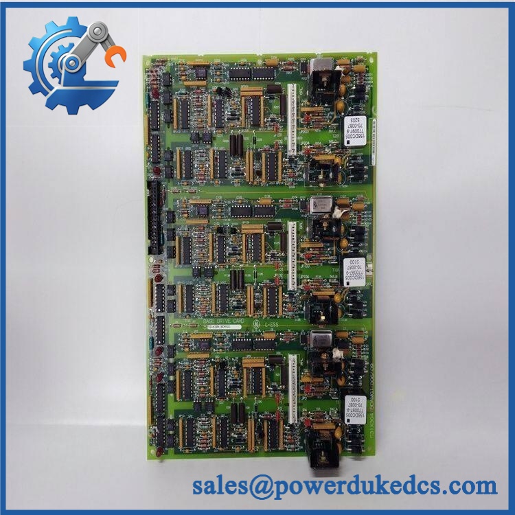
GE 531X304IBDASG1
Application Scenarios & Pain Points
Micro-case — drive startup fault: An drive receives its expected control power, yet the power stage does not respond correctly to the control command. Once the incoming supply, external wiring, and associated control cards have been checked, the base-drive card becomes a logical hardware fault candidate.
For industrial motor-drive systems, the base-driver section is positioned close to the power-conversion circuitry and therefore has a different failure profile from a simple signaling PCB. Thermal stress, switching-device faults, connector problems, and degraded discrete components all warrant inspection.
In legacy production equipment, maintaining an exact board can avoid unnecessary replacement of an entire drive assembly. This matters when the motor, cabinet, feedback wiring, and plant control interface are still tied to the installed architecture.
At 50°C+ cabinet temperatures, inspect the six heatsinks, transformer areas, nearby capacitors, and solder joints carefully. Heat-related degradation can be progressive, producing intermittent drive faults before the board fails completely.
With versus without a verified spare: a tested 531X304IBDASG1 can reduce the diagnostic path for a failed legacy drive; an unverified board can introduce unknown jumper settings or an electrically incompatible revision.
🚨 Common Error Codes & Diagnostic Symptoms
No authoritative GE fault-code list specific to 531X304IBDASG1 was located. The following are therefore hardware symptoms rather than official numerical codes.
Symptom/Code: Drive fails to deliver expected base-drive response → Diagnosis: Possible fault in the base-driver interface, transformer section, switching devices, connector path, or associated control circuitry → Action: Verify the upstream control and drive power sections, then replace the board when the fault follows the 531X304IBDASG1.
Symptom/Code: Repeated drive trips during startup with otherwise normal control logic → Diagnosis: A degraded driver section or abnormal feedback/protection path may be preventing proper power-device switching → Action: Check the power bridge and protection feedback first; replace the base-drive card when board-level failure is confirmed.
Symptom/Code: One functional section behaves differently from the other two → Diagnosis: The board’s three repeated sections allow comparative diagnosis; a single abnormal section may indicate a local transformer, transistor, diode, resistor-network, connector, or jumper-related fault → Action: Compare the affected section against a known-good reference and replace the PCB when the fault is localized to the board.
🚨 Cross-Reference & Lifecycle Migration
Cross-Reference
The primary identification is:
GE 531X304IBDASG1 → Base Drive Card
This description is supported by multiple industrial parts references.
A secondary parts record associates F31X304IBDAMG1-006 with the 531X304IBDASG1 family. This should be considered a board-level identification reference, not an automatic statement that every F31X304IBDAMG1-006 assembly is electrically interchangeable with every 531X304IBDASG1.
A related listing identifies 531X304IBDARG1 as another Base Drive Card and indicates that a later procurement entry uses 531X304IBDASG1 in place of the R revision. That provides useful lifecycle information, but direct replacement should still be confirmed against the original drive documentation and PCB revision.
Firmware Requirement
The 531X304IBDASG1 is a hardware drive card, not a modern programmable controller. No user firmware flashing procedure was established for this exact board.
Replacement compatibility instead depends on:
- Drive model
- Board revision
- Jumper configuration
- Connector arrangement
- Associated control cards
- Power-stage architecture
Lifecycle Status
Lifecycle: Legacy / Obsolete.
The 531X family belongs to older GE drive technology and is now handled mainly through specialist replacement, surplus, and repair channels. Current parts databases continue to list the 531X304IBDASG1, while related revision records show older variants being superseded or handled through repair programs.
For a critical installed base, stock should be managed as controlled legacy inventory. Record the exact suffix, physical revision, jumper settings, and host-drive identification with each spare.
Field Engineer’s Tech Notes
First warning: photograph every jumper before removing the board. The published construction description specifically identifies jumper switches on the board. A replacement PCB with an incorrect jumper arrangement can appear electrically healthy and still behave incorrectly in the host drive.
Second warning: do not overlook the heatsink and transformer sections. This card contains three transformers and six heatsinks. Thermal discoloration, cracked solder around heavy components, or abnormal resistance in one repeated section can provide a useful clue (compare the three sections instead of inspecting them in isolation).
Use ESD controls whenever the PCB is outside its enclosure. Avoid touching the exposed connector contacts.
Strict QA & Testing SOP
1. Inbound identification
Confirm 531X304IBDASG1 on the physical PCB. Record every board-level marking, including any F31X number, revision information, manufacturing code, and labels.
2. Visual inspection
Inspect the PCB for cracked components, corrosion, carbonized areas, solder damage, lifted pads, damaged connectors, and evidence of previous repair.
3. Component inspection
Examine the three transformers, six heatsinks, transistors, capacitors, diodes, resistor networks, and jumper switches. Pay particular attention to heat-affected areas.
4. Connector verification
Compare the three vertical pin-header locations and all associated interfaces with the customer’s removed board. Mechanical similarity alone is not enough for acceptance.
5. Jumper verification
Record all jumper positions and compare them against the original board or approved drive configuration before applying power.
6. Electrical pre-check
Perform controlled continuity, resistance, and isolation checks on the applicable power and signal paths. Do not use unverified reseller voltage figures as acceptance limits.
7. Controlled drive-rig test
Install the board into a compatible test assembly. Confirm control-interface behavior, driver operation, protection feedback, and the absence of abnormal trip conditions.
8. Comparative section testing
Where the test fixture permits, compare the three repeated functional sections for consistent electrical behavior and thermal response.
9. Extended observation
Operate the drive under an approved representative load while monitoring heatsink temperatures, supply behavior, fault indications, and switching stability.
10. Final preservation
After passing inspection, place the PCB in ESD shielding packaging, protect connectors, add impact cushioning, and retain the complete QC record.
Test videos are available when live-rig testing is performed and visual evidence is required for procurement approval.
Buyer’s FAQ
Is GE 531X304IBDASG1 a complete drive?
No. It is identified as an Base Drive Card, meaning it is a PCB-level component within the drive architecture. It should not be described or quoted as a complete drive assembly.
Can I substitute 531X304IBDARG1 or another 531X304 board?
Not automatically. Related part numbers exist, but revision and configuration differences matter. One current parts record specifically indicates 531X304IBDARG1 is associated with a use of 531X304IBDASG1, which is useful for lifecycle research but should be confirmed against the actual drive before substitution.
Can this board be hot-swapped?
Do not assume so. The board is part of the drive’s power-control architecture and may be connected to hazardous energy even when the motor is stopped. De-energize, isolate, and discharge the drive according to the applicable GE maintenance procedure before removing the PCB.
How do I verify New Original condition and warranty?
Request photographs of the actual 531X304IBDASG1, including all GE/F31X identification markings, board revision, jumper positions, transformers, heatsinks, connectors, and packaging. The commercial document should state whether the unit is New Original, New Surplus, refurbished, or repaired, together with the test scope and warranty period.
For legacy inventory, maintain a controlled record containing 531X304IBDASG1 + board revision + alternate F31X marking + jumper configuration + host drive model + QC result + COO + packaging condition.











 Start Chat


