

Description
- Model & Brand: GE General Electric 531X305NTBAPG1
- Series: EX2000 Excitation / 531X Drive Control
- Part Type: NTB/3TB Terminal Board
- Physical Dimensions: Approximately 160 × 160 × 120 mm (W × H × D) for the commonly listed assembly envelope; confirm the actual board and mounting arrangement before cabinet documentation.
- Estimated Shipping Weight: Approximately 1.0 kg according to supplier records; another distributor lists 2 kg shipping weight, so actual packed weight should control freight documents.
- What’s in the Box: 531X305NTBAPG1 terminal board, ESD protection, rigid PCB protection, and applicable inspection/QC documentation. Mating cables, external controller boards, encoder, power supply, and cabinet mounting hardware are not assumed.
Product Introduction
The GE 531X305NTBAPG1 is installed in the EX2000 excitation or related 531X drive cabinet as an NTB/3TB terminal board, providing the physical landing point for a broad range of external signal-level connections. Rather than functioning as a processor or standalone I/O controller, it ties field wiring to the associated control and power circuitry through multiple plug interfaces.
Its interface functions include regulated and unregulated power distribution, digital inputs, relay outputs, low-level analog signal handling, and an A-quad-B encoder interface with marker channel. Hardware jumpers determine important signal conditions, including encoder supply selection and input biasing (which should be documented before any board exchange).
Core Technical Specifications
| Parameter | Value |
|---|---|
| Manufacturer | GE General Electric |
| Model | 531X305NTBAPG1 |
| Series | 531X / EX2000 |
| Product Type | NTB/3TB Terminal Board |
| Primary Function | External signal-level I/O termination and interface |
| Regulated Supply | +5 VDC, 300 mA |
| Regulated Supply | +15 VDC, 300 mA |
| Unregulated Supply | 24 VDC, 500 mA |
| AC Output | 120 VAC, 0.5 A |
| General-Purpose Inputs | 12 inputs |
| Digital Input Voltage | Up to 24 VDC |
| Input Bias | Jumper-selectable +24 VDC or -24 VDC |
| Relay Outputs | 7 relay outputs |
| Relay Configuration | Form A / Form C, application dependent |
| Relay Contact Voltage | Up to 120 VAC |
| Encoder Interface | Differential A-quad-B with marker channel |
| Encoder Supply Selection | +5 VDC or ±15 VDC via jumpers |
| Analog Interface | Low-level analog I/O, application dependent |
| Potentiometers | 4 for signal scaling/adjustment |
| Internal/Control Connections | 6PL, 8PL, 2PL, 4PL, COMPL and related interfaces |
| Processor | None |
| User Memory | None |
| Standalone Firmware | None |
| Power Consumption | Load-dependent |
| Heat Dissipation | Load-dependent |
| Approx. Dimensions | 160 × 160 × 120 mm |
| Estimated Weight | Approximately 1 kg, configuration and packaging dependent |
| Mounting | Internal EX2000/531X cabinet |
| Configuration | Hardware jumpers and system wiring |
| Hot Replacement | Do not assume live replacement |
| Lifecycle Position | Legacy / Obsolescence-Controlled |
The board provides several power rails that can be used by the associated drive/excitation electronics and external equipment. Available records identify +5 VDC and +15 VDC at 300 mA, 24 VDC at 500 mA, and 120 VAC at 0.5 A.
The twelve general-purpose digital inputs can be biased through hardware jumpers for positive or negative logic. The encoder interface also uses jumper selection, so the physical configuration is part of the engineering identity rather than a minor setup detail.
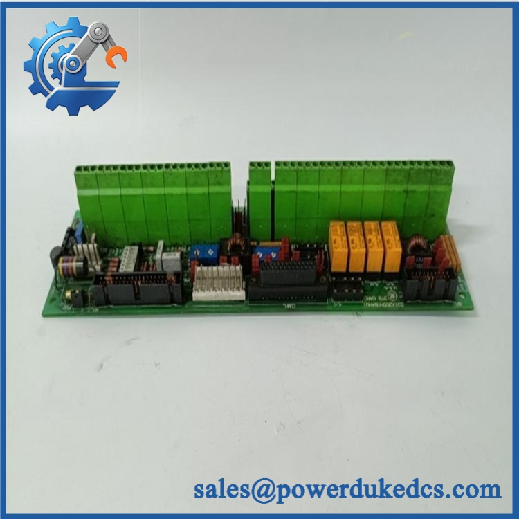
GE 531X305NTBAPG1
🚨 Global Compliance & Industry Certifications
The 531X305NTBAPG1 is a legacy EX2000/531X terminal-board assembly, so regulatory claims should be evaluated against the complete excitation or drive cabinet.
- CE Mark: Verify against the applicable GE EX2000/531X equipment documentation and production revision.
- UL/cUL: Confirm the certification of the complete installed control/excitation equipment rather than assuming approval for the bare terminal board.
- ATEX / IECEx: Do not assume standalone hazardous-area certification for the 531X305NTBAPG1.
- Marine approvals: DNV GL or another marine approval should not be assumed without project-specific documentation.
- Electrical safety: The board carries multiple DC rails and a 120 VAC circuit, so correct isolation and cabinet wiring are essential.
- Country of Origin: Establish from actual manufacturing traceability.
- HS Tariff Classification: Confirm the final tariff code with the destination-country customs broker.
A terminal board may participate in a certified excitation system without carrying every system certification as an independent PCB. That distinction should remain explicit in audit files.
Verify specific lot certifications with OEM.
🚨 Long-Term Storage & Asset Preservation Guide
Keep the 531X305NTBAPG1 in an ESD shielding bag and protect every terminal and plug interface from dust and oxidation. The board has numerous interconnects, so contamination at one connector can produce an intermittent fault that resembles a control-board failure.
Store it in a dry, stable warehouse without condensation. A practical long-term target below approximately 60% RH helps reduce corrosion risk, particularly around exposed terminals and connector contacts.
Before release, compare the stored board’s jumper positions, potentiometer settings, connector labels, and fuse/protection configuration with the original asset record. Photograph those settings; relying on memory during an outage is poor practice.
Do not energize a long-stored board using an assumed supply voltage. The board contains several different supply circuits, including a 120 VAC output, so controlled testing should follow the appropriate GE procedure.
Physical Installation Prerequisites
Install the 531X305NTBAPG1 only in the specified /531X cabinet assembly and preserve the original board orientation and mounting points.
Verify the complete power arrangement before wiring. Available documentation identifies +5 VDC, +15 VDC, 24 VDC, and 120 VAC circuits, so field technicians must trace each connection against the cabinet schematic before energizing.
Record every jumper before removing the old board. In particular, verify the encoder supply selection and the digital-input bias arrangement. An incorrect jumper can produce an apparently healthy board with electrically incorrect field behavior.
Maintain cabinet grounding, shield termination, and cable segregation according to the original installation design. Keep encoder and low-level analog wiring separated from high-energy switching conductors where the cabinet layout permits.
Do not impose an arbitrary 50 mm clearance requirement on this legacy board. Preserve the original GE cabinet spacing, ventilation path, and service access instead.
Do not remove or install the board while energized unless the approved GE maintenance procedure specifically permits that operation.
Buyer’s FAQ — Logistics & Compliance Focus
Q: What HS Tariff Code should be used for 531X305NTBAPG1?
A: It is a specialized industrial terminal/interface board, but the final Harmonized System classification depends on the importing country’s tariff schedule and customs interpretation. Have the importer or broker confirm the code before the commercial invoice is finalized.
Q: Does the shipping location establish Country of Origin?
A: No. COO should be supported by manufacturing or traceability documentation for the actual 531X305NTBAPG1 or production lot. Supplier location and export port do not independently establish manufacturing origin.
Q: Does this terminal board include the latest firmware pre-loaded?
A: No. The 531X305NTBAPG1 is an interface/termination board with no standalone programmable application firmware. Its relevant configuration is established through hardware jumpers, wiring, connected control electronics, and the /531X system configuration.
Q: How should shipping insurance and physical packing be handled?
A: Insure the board for its documented replacement value and retain photographs of the complete part number, connectors, jumper positions, and board condition before dispatch. Use ESD shielding, rigid connector protection, moisture-resistant packaging, and internal cushioning; distributor records vary between approximately 1 kg and 2 kg shipping weight, so the actual packed measurement should be used on the freight documents.











 Start Chat


