

Description
- Model: GE 531X307LTBAJG1
- Brand: GE / General Electric
- Series: 531X
- Part Type: LAN I/O Terminal Board (LTB)
- Core Function: Interfaces external discrete field devices with GE drive and excitation control electronics, converting supported field-voltage signals into internal logic-level signals.
- Key Specifications: 8 configurable control-input channels; 2–240 VAC/DC field-input range; 8PL internal bus interface; 7 documented Form C relay outputs; approximately 202 × 261 × 21 mm and 0.36 kg in current technical records.
- Typical Systems: GE AC/DC2000, EX2000, EX2100, and Mark V drive/excitation architectures.
Product Introduction
The GE 531X307LTBAJG1 sits at the field-interface layer of older GE drive and excitation cabinets. External devices such as pushbuttons, switches, breaker contacts, interlocks, and indicators can be terminated through the LTB, while the board passes the required signals toward the control electronics. GE parts references identify the exact assembly as a LAN I/O Terminal Board in the 531X family.
For the G1 design, published technical descriptions identify eight configurable control-input connections and an 8PL bus interface linking the board with the associated control/terminal architecture. The field inputs can accept a broad 2–240 VAC/DC range, with the input circuitry converting qualifying signals to a 24 VDC logic representation. Seven three-terminal relay output groups are also documented (check the actual terminal markings before wiring because some aftermarket descriptions incorrectly count the output channels).
Core Technical Specifications
| Parameter | Value |
|---|---|
| Manufacturer | GE / General Electric |
| Exact Part Number | 531X307LTBAJG1 |
| Product Family | 531X Boards |
| Board Designation | LTBA |
| Product Type | LAN I/O Terminal Board |
| Control Inputs | 8 configurable inputs |
| Field Input Range | 2–240 VAC/DC |
| Internal Logic Level | 24 VDC |
| Approx. Turn-On Threshold | 9 V / 4.6 mA |
| Approx. Turn-Off Threshold | 6 V / 1.0 mA |
| Relay Outputs | 7 documented Form C relay groups |
| Relay Contact Format | Three terminals per relay group |
| Internal Bus Interface | 8PL ribbon-cable connection |
| Field Connections | Screw-terminal interface |
| Related Systems | AC/DC2000, EX2000, EX2100, Mark V |
| Board Dimensions | Approx. 202 × 261 × 21 mm |
| Unit Weight | Approx. 0.36 kg |
| Firmware | None as a standalone programmable module |
| Mounting | Internal drive/excitation cabinet |
| Cooling | Dependent on host cabinet airflow |
| Standalone Power Consumption | Not reliably established from an OEM source |
| Standalone Heat Dissipation | Not reliably established from an OEM source |
| Exact Operating Temperature | To be verified from host-equipment documentation |
| Exact Storage Temperature | To be verified from host-equipment documentation |
| Lifecycle | Legacy / obsolete |
The eight input channels, 2–240 VAC/DC range, internal 24 VDC logic interface, and 8PL bus connection are supported by multiple current technical records. The physical dimensions and 0.36 kg weight are also reported consistently by specialist listings.
Power and Thermal Note
A dependable GE OEM value for the board’s independent power consumption was not located. Do not insert a generic 531X PCB wattage into an approved cabinet heat-load calculation.
The LTB is installed within a larger drive or excitation assembly, so actual thermal conditions depend on the host system, field loading, surrounding electronics, cabinet temperature, and airflow. A 50°C+ cabinet ambient deserves specific review before relying on historical board-life assumptions.
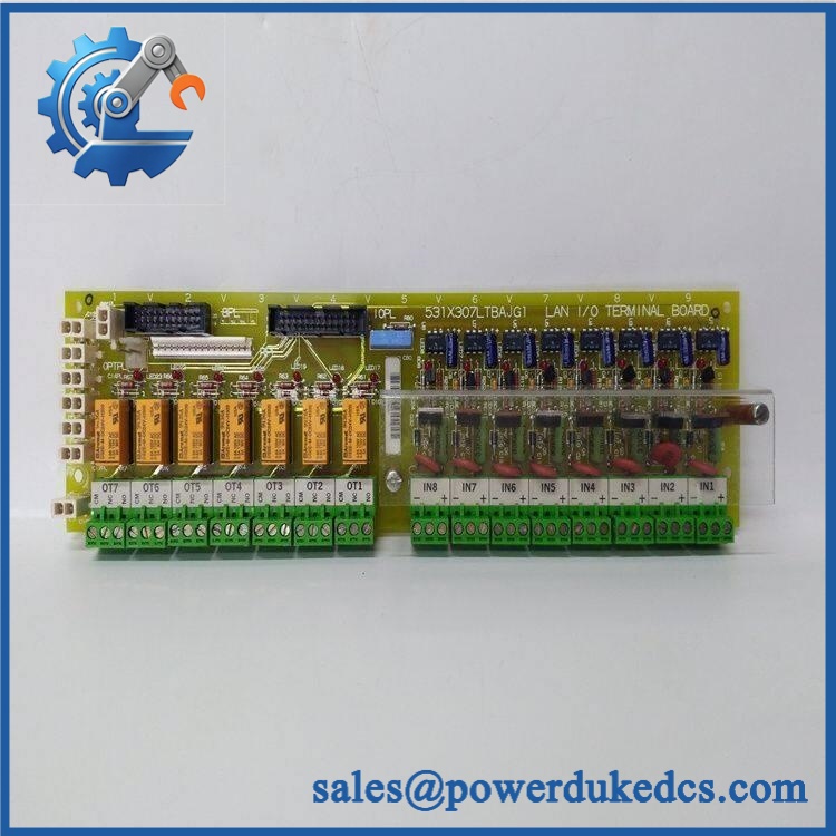
GE 531X307LTBAJG1
Application Scenarios & Pain Points
A Mark V cabinet loses one permissive signal while the external contact itself tests correctly. The LTB is one of the first assemblies to inspect because it converts field signals and passes them through the internal 8PL architecture to the controller. A failed input channel, connector, or board-level component can interrupt the signal path even when the field device is healthy.
Within EX2000 excitation equipment, the board provides a field interface for external control devices. The wide 2–240 VAC/DC input range allows the same board architecture to accommodate different discrete signal voltages used by the surrounding equipment.
For AC/DC2000 drive cabinets, relay outputs provide low-voltage, low-current contact interfaces for downstream control or indication functions. The exact output assignment remains installation-specific and should be checked against the cabinet schematic before replacement.
During legacy Mark V maintenance, physical connector condition can be the real failure point. The board uses an 8PL ribbon interface plus multiple terminal strips; vibration, oxidation, loose terminal screws, or mechanical stress can produce intermittent symptoms (especially after cabinet work).
🚨 Common Error Codes & Diagnostic Symptoms
The 531X307LTBAJG1 does not provide an independent software fault-code system. Diagnostic indications normally originate from the host GE drive or excitation controller.
Symptom/Code: Field permissive present, controller input remains inactive → Diagnosis: Check the corresponding LTB input, field voltage, connector, terminal wiring, and 8PL path. An input-conditioning fault can prevent a valid field signal from becoming the expected 24 VDC logic state. → Action: Verify the field signal and channel electrically; replace the board if the input path fails controlled testing.
Symptom/Code: Commanded relay output does not transfer → Diagnosis: Possible causes include a failed relay coil/contacts, damaged PCB soldering, incorrect terminal wiring, or excessive external loading. → Action: Test the relevant Form C contacts under controlled conditions and replace the board if the relay channel is confirmed defective.
Symptom/Code: Several inputs and outputs fail together → Diagnosis: A common 8PL connection, board supply, or host-interface problem is more likely than multiple simultaneous independent channel failures. → Action: Inspect the common interface first, then substitute a known-good board if the fault follows the LTB.
🚨 Cross-Reference & Lifecycle Migration
The 531X307LTBAJG1 has a related GE identifier:
- F31X307LTBAJG1 is documented as a related LAN I/O Terminal Board, with the 531X307LTBAJG1 shown as its secondary number. The F31X version is described with two vertical male cable connectors, two header connectors, eight two-position plugs, and fifteen three-position terminal strips.
- The same 531X307 family includes LTBACG1, LTBAFG1, LTBAHG1, LTBAKG1, and other suffixes. These are related terminal-board assemblies, not automatically interchangeable parts.
- A G2 version is also documented in the 531X307 family. Current technical records specifically state that the G1 design has the additional 8PL/CI input arrangement, while the G2 configuration differs.
Therefore, do not approve a replacement solely because it is another 531X307 board. Check the suffix, terminal labeling, internal connector arrangement, host equipment, and cabinet schematic.
Firmware: No standalone field firmware applies to this board. It is a hardware interface assembly.
Lifecycle status: Legacy / obsolete. Current specialist suppliers continue to list the exact part, and current secondary inventories include new-surplus and repair channels.
For buffer-stock control, preserve the exact LTBAJG1 suffix and the host-system application. A generic “LAN I/O terminal board” warehouse entry is too broad.
Field Engineer’s Tech Notes
Warning 1 — Do not assume every input terminal is a 24 VDC-only point.
The G1 design is documented for 2–240 VAC/DC field inputs, with the board converting the received signal to a 24 VDC logic representation. Check the actual circuit and terminal designation before applying a test voltage; an incorrect test setup can damage field-interface circuitry.
Warning 2 — Document the 8PL connection before removal.
The ribbon interface links the LTB with the associated control architecture. Photograph its orientation and cable routing before disconnection, then inspect the mating contacts for contamination or mechanical damage (a poor connection here can imitate several failed I/O channels at once).
Strict QA & Testing SOP
Step 1 — Incoming identity check
Confirm 531X307LTBAJG1, visible board markings, revision information, and any secondary F31X identification.
Step 2 — Physical inspection
Examine the PCB for corrosion, burned components, cracked solder joints, lifted traces, damaged terminal strips, broken supports, and previous repair work.
Step 3 — Connector inspection
Inspect the 8PL connector, control-input plugs, relay connections, and terminal strips. Check for oxidation, bent contacts, loose hardware, and cracked connector bodies.
Step 4 — Input-channel testing
Apply controlled AC/DC signals to representative channels, beginning at low voltage and progressing only within the approved test procedure. The documented field-input range is 2–240 VAC/DC.
Step 5 — Threshold verification
Where the test procedure supports it, verify switching behavior near the reported 9 V turn-on / 6 V turn-off thresholds. Treat these values as technical reference figures rather than a substitute for the original GE acceptance specification.
Step 6 — Relay testing
Operate each available relay channel under a current-limited test condition. Verify Form C contact transitions, continuity, and contact behavior.
Step 7 — 8PL interface test
Install the board into a compatible test assembly and confirm that input and output states are correctly transferred through the internal interface.
Step 8 — System-level test
Where a suitable GE drive or excitation test setup is available, exercise representative permissive, interlock, indication, alarm, and relay-output functions.
Step 9 — Thermal observation
Run the board under representative loading and inspect for abnormal heating around relays, input circuits, connectors, and power-conditioning components.
Step 10 — Documentation
Record part number, revision, channels tested, test voltages, relay results, host test assembly, inspection photographs, and QA disposition.
Step 11 — Final packaging
Place the accepted board in ESD shielding packaging with rigid protection around the PCB and connector areas.
Test videos are available for qualifying inventory when pre-shipment inspection evidence is required.
Buyer’s FAQ
Q1. Can I hot-swap the 531X307LTBAJG1?
Do not assume live replacement is permitted. The board interfaces external field circuits within GE drive and excitation equipment, and the actual cabinet can contain hazardous AC/DC sources.
Follow the host equipment’s lockout/tagout and discharge procedure before removing the LTB.
Q2. How do I verify a New Original unit?
Request photographs of the actual 531X307LTBAJG1, including the part-number marking, revision, 8PL connector, terminal side, relay section, and overall PCB layout.
For New Original procurement, retain the original packaging and available traceability information. A photograph of another 531X307 variant does not establish exact identity.
Q3. What warranty should be specified?
Warranty is supplier-specific. Current specialist listings show examples ranging from 12 months to 3 years, depending on supplier and inventory condition. These are commercial supplier warranties rather than a universal GE factory warranty.
The purchase order should state the exact condition and warranty period.
Q4. Does this board require firmware loading?
No standalone firmware package has been identified for the 531X307LTBAJG1. It is a hardware I/O terminal interface rather than a programmable processor.
Lifecycle & Asset-Control Note
The GE 531X307LTBAJG1 is a legacy LAN I/O Terminal Board associated with GE drive and excitation systems, including AC/DC2000, EX2000, EX2100, and Mark V applications.
For controlled spare inventory, retain the complete part number, board revision, F31X cross-reference where applicable, 8PL configuration, terminal arrangement, host equipment, COO, certification evidence, QA status, and storage history. The G1 suffix should not be collapsed into a generic 531X307 stock code because related G1/G2 and other suffix variants have different interface configurations.











 Start Chat


