

Description
-
Brand: GE
- Full Model Number: 531X310NDAEG1
- Product Type: Drive Control / Interface Board
- System/Series Family: GE 531X Series
- Core Function: Drive control and interface board for compatible GE 531X adjustable-speed drive systems
- Top 3 Hardcore Specs: 531X platform | Drive control board | NDAEG1 configuration
- Board Family: 531X
- Application: Adjustable-speed AC/DC drive control
- Stock Status: New surplus / condition to be confirmed per available unit
Module 3: Technical Product Introduction
A failed control board in a legacy adjustable-speed drive can stop the entire drive system even when the motor, power section, and incoming supply remain healthy. GE 531X310NDAEG1 belongs to the GE 531X family of drive control/interface boards, providing the electronic control and interface functions required by compatible 531X drive equipment. Correct identification is especially important because 531X boards were produced in multiple configurations for different drive functions.
The complete 531X310NDAEG1 ordering code should be used when sourcing a replacement rather than relying on the generic 531X family designation. Public technical information for this exact suffix does not provide enough reliable evidence to state definitive processor, memory, input/output, or communication specifications. —For an older drive, the installed board revision and associated option hardware can matter more than a generic product-family description. Verify the original board markings and drive model before approving substitution.
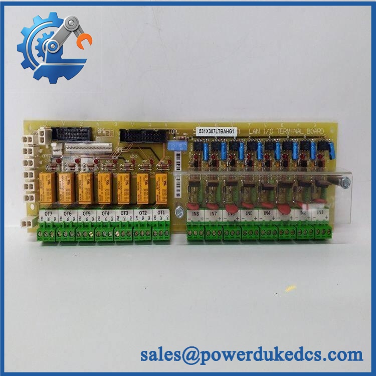
GE 531X310NDAEG1
Module 4: Application Scenarios & Field Realities
- On legacy adjustable-speed drive systems, the 531X control board can provide the control and interface layer between the drive’s command circuitry and power section. When a drive refuses to start, verify control power, feedback signals, and interface connections before replacing the board.
- During drive maintenance, record every connector and cable position before removal. A reversed harness can create multiple secondary faults and make a successful board replacement appear defective.
- For older production machinery where the original drive cannot be easily replaced, maintaining the correct 531X board can preserve the existing motor-control architecture without requiring a complete cabinet redesign. Confirm the exact drive model and board configuration first.
- When diagnosing intermittent drive trips, inspect the board’s connectors and surrounding cabinet conditions. Vibration, contamination, loose connections, and elevated temperature can cause intermittent behavior that disappears during a short bench inspection.
Module 5: Migration, Compatibility & Installation Traps
Replacement Matrix
| Replacement Type | 531X310NDAEG1 Assessment |
|---|---|
| Drop-in Replacement | Potentially yes, when replacing the same 531X310NDAEG1 configuration in a compatible GE 531X drive |
| Software Compatible | Configuration-dependent; drive parameters and option configuration must be verified after installation |
| Hardware Modification Required | Not expected for an exact replacement; required if board configuration, connectors, or drive architecture differ |
Field Traps — Watch Out
1. Do not substitute by the 531X family alone.
The complete 531X310NDAEG1 designation should match the installed board or an approved GE replacement reference. Different 531X boards can have different functions, connector arrangements, and drive compatibility.
2. Preserve drive parameters.
Before removing a functioning board during planned maintenance, record the drive’s configured parameters and option settings. A replacement control board may restore hardware operation without restoring the original application-specific settings.
3. Check feedback and command wiring.
Verify speed reference, enable, fault, feedback, and other control connections against the cabinet schematic. Incorrect signal routing can produce an apparent control-board failure.
4. Inspect the surrounding power electronics.
If the original board failed after a power-stage event, do not install the replacement without investigating the underlying fault. A defective power component, feedback circuit, or auxiliary supply can damage the new board.
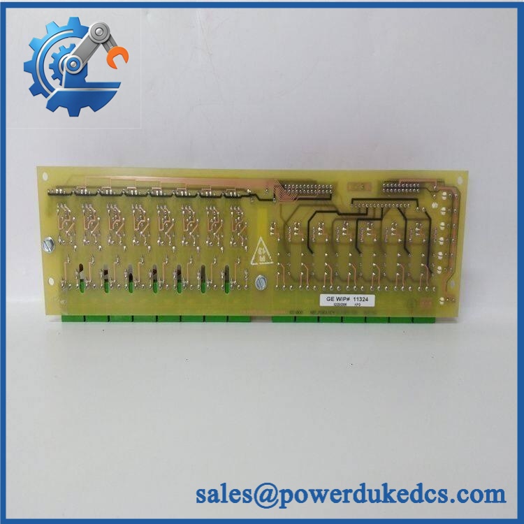
GE 531X310NDAEG1
Module 6: Quality Assurance SOP
Before shipment, each available GE 531X310NDAEG1 should pass a documented inspection sequence:
- OEM identification inspection — Verify GE markings, complete 531X310NDAEG1 designation, board labels, revision information, and serial/lot markings where available.
- OEM anti-counterfeit visual inspection — Examine PCB construction, component markings, connectors, labels, solder joints, and evidence of unauthorized repair or component replacement.
- Physical inspection — Check the PCB, board edges, connector interfaces, mounting points, terminal areas, and exposed components for cracks, corrosion, contamination, or impact damage.
- Part-number verification — Confirm the physical board against the customer’s exact 531X310NDAEG1 requirement before electrical testing.
- Controlled power-on test — Apply the appropriate test supply using a protected laboratory setup and verify normal initialization without abnormal current draw.
- Interface verification — Check applicable control, feedback, and communication interfaces using an approved test procedure.
- Drive-system simulation — Where a compatible 531X test setup is available, verify representative command and feedback functions under controlled conditions.
- Diagnostic verification — Check available board and drive diagnostics for hardware faults, abnormal status, or intermittent behavior.
- Extended stability test — Operate the board in a suitable test environment and monitor for resets, thermal abnormalities, signal loss, or communication faults.
- Final visual inspection — Recheck connectors, labels, mounting features, and PCB condition after testing.
- Test record and packaging — Record the part number, revision, test results, inspection date, and packaging condition before dispatch.
QA note: The 531X310NDAEG1 is a drive control/interface board, so a generic PLC RUN/ERR POST procedure should not be claimed unless the exact hardware provides those diagnostics. Controlled power-up, interface verification, drive-system simulation, and extended stability testing are more appropriate acceptance checks.











 Start Chat


