

Description
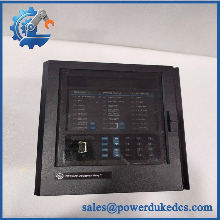
- Model & Brand: GE Multilin 760-P1-G1-S1-LO-A20-R-E
- Series: GE Multilin 750/760 Feeder Management Relay
- Part Type: 760 Feeder Management Relay, drawout unit
- Configuration: 1 A phase CT, 1 A zero-sequence CT, 1 A sensitive-ground CT, low control power, eight 4–20 mA analog outputs, red breaker-closed LED, enhanced display with Ethernet
- Physical Dimensions: Approximately 7.0 × 9.0 × 7.0 in. (17.8 × 22.9 × 17.8 cm) for the drawout unit/packaging envelope commonly documented by suppliers. Verify the complete case and panel arrangement before cabinet work.
- Estimated Shipping Weight: Approximately 5.1 kg / 11.25 lb shipping weight for the relay and case; exact export-packed weight should control freight documents.
- What’s in the Box: 760 relay drawout unit, protective packaging, and applicable inspection/QC documentation. The external case, CTs, RS-232/RS-485 converter, mounting collar, and other accessories are configuration-dependent and should not be assumed unless expressly included.
Product Introduction
The GE Multilin 760-P1-G1-S1-LO-A20-R-E is a configured 760 Feeder Management Relay for protection, measurement, control, and autoreclose functions on distribution feeders. This exact order code specifies 1 A phase-current inputs, 1 A zero-sequence current inputs, 1 A sensitive-ground current input, low-voltage control power, eight 4–20 mA analog outputs, a red breaker-closed indicator, and the enhanced display with Ethernet.
Configuration identity matters here. The last characters are not cosmetic: LO selects low control power, A20 selects eight 4–20 mA outputs, R selects the red breaker-closed LED, and E selects the enhanced display with Ethernet. The relay is a fully drawout unit with automatic CT shorting, while the complete case is normally a separate mechanical component (which should be stated clearly on the purchase order).
Core Technical Specifications
| Parameter | Value |
|---|---|
| Manufacturer | GE Multilin / General Electric |
| Model | 760-P1-G1-S1-LO-A20-R-E |
| Product Family | 750/760 Feeder Management Relay |
| Base Relay | 760 |
| Relay Function | Feeder protection, management, control, and autoreclose |
| P1 | 1 A phase-current inputs |
| G1 | 1 A zero-sequence current inputs |
| S1 | 1 A sensitive-ground current input |
| LO | 20–60 VDC / 20–48 VAC, 48–62 Hz |
| A20 | 8 active 4–20 mA analog outputs |
| R | Red breaker-closed LED |
| E | Enhanced display with Ethernet |
| System Voltage | 3- or 4-wire systems, up to 600 kV |
| Maximum System Current | Up to 5000 A |
| Frequency | 25–60 Hz nominal; frequency tracking 16–65 Hz |
| Phase CT Input | 1 A secondary |
| Phase Conversion Range | 0.01–20 × CT |
| Phase Accuracy | ±0.5% of 2×CT below 2×CT; ±1% of 20×CT at or above 2×CT |
| Phase CT Overload Withstand | 80× rated current for 1 s; 3× continuously |
| Ground CT Input | 1 A secondary |
| Sensitive Ground Burden | <0.2 VA at 1 or 5 A |
| Voltage Input | 50–240 V phase-neutral |
| Maximum Voltage | 273 V phase-neutral continuous |
| Voltage Accuracy | ±0.25% FS from 11–130 V; ±0.8% FS from 130–273 V |
| Logic Inputs | 14 contact/virtual inputs + 6 virtual-only |
| Dry Contact Input | 1000 Ω maximum ON resistance |
| Wet Contact Input | 30–300 VDC at 2 mA |
| Analog Input | Programmable 0–1, 0–5, 0–10, 0–20, or 4–20 mA |
| Analog Input Impedance | 375 Ω ±10% |
| Analog Input Accuracy | ±1% FS |
| Analog Outputs | 8 × 4–20 mA, active, fully isolated |
| Analog Output Load | 600 Ω maximum |
| Analog Output Accuracy | ±1% FS |
| Analog Output Response | < 100 ms to 100% indication |
| Output Relays | 8 |
| Trip/Close Relay Type | Form A |
| Auxiliary/Self-Test Relays | Form C |
| Trip/Close Carry Rating | 10 A at 250 VAC continuous |
| Service Relay Carry Rating | 5 A at 250 VAC continuous |
| Trip/Close DC Break Rating | 0.4 A at 250 VDC, L/R 40 ms |
| Service DC Break Rating | 0.3 A at 250 VDC, L/R 40 ms |
| Communications | RS-232, RS-485/422, Ethernet |
| Protocols | Modbus RTU / DNP 3.0 |
| Ethernet | 10Base-T RJ45, Modbus TCP/IP on Ethernet option |
| Maximum Ethernet Sessions | 4 |
| Clock Resolution | 1 ms |
| IRIG-B Accuracy | ±1 ms |
| Supercapacitor Backup | Approximately 45 days with control power off |
| Control Power Consumption | 25 VA nominal; 35 VA maximum |
| Operating Temperature | -40°C to +60°C |
| Storage Temperature | -40°C to +80°C |
| Humidity | Up to 90% RH, non-condensing |
| Pollution Degree | 2 |
| Protection Rating | IP40 front / IP20 rear |
| Case | Fully drawout, automatic CT shorting |
| Mounting | Panel or 19-inch rack mount |
| Complete Relay + Case Weight | 7.9 kg |
| Shipping Weight | 9.4 kg in GE manual; supplier shipping records for this order code may list ~5.1 kg for the drawout unit |
| Firmware | Field-upgradeable |
| Hot Replacement | Follow drawout/CT-short maintenance procedure; do not assume unrestricted live replacement |
| Lifecycle Position | Legacy / Lifecycle-Controlled |
The exact order code decodes cleanly against the GE 750/760 ordering structure. P1/G1/S1 specify the 1 A current-input configuration; LO specifies low control power; A20 selects eight 4–20 mA analog outputs; R selects the red breaker-closed indicator; and E denotes the enhanced display with Ethernet.
For the low-control-power configuration, GE specifies 20–60 VDC or 20–48 VAC at 48–62 Hz, with 25 VA nominal and 35 VA maximum power consumption. That is important for panel power-budgeting because the relay’s control-power demand is materially different from a simple 24 VDC electronic indicator.
GE 760-P1-G1-S1-LO-A20-R-E
🚨 Global Compliance & Industry Certifications
The GE 750/760 documentation provides an identifiable approval and test framework for this relay family:
- CE Mark: The 750/760 manual identifies conformity to applicable European requirements, including IEC 1010-1 / EN 50082-2, with EMC requirements addressed for Europe.
- UL/cUL: The relay family is identified as UL listed for the USA and Canada, E83849.
- FCC: Part 15 requirements are identified for RF emissions in North America.
- ACA / Australia: The documentation identifies an ACA mark for RF emissions.
- ATEX / IECEx: Do not assume hazardous-area certification for this exact relay configuration merely from CE/UL status. Verify the certificate for the actual installed configuration.
- Marine / DNV GL: No DNV GL approval should be assumed for the exact unit without project-specific evidence.
- Insulation Testing: The 750/760 type-test data includes 2300 VAC dielectric-strength testing and insulation resistance greater than 100 MΩ at 500 VAC for 10 s.
- Country of Origin: Establish from actual manufacturing traceability.
- HS Tariff Classification: Confirm the final classification with the destination-country customs broker.
A key safety point is the relay’s fully drawout design with automatic CT shorting. This reduces the risk associated with withdrawing a relay connected to current transformers, but technicians must still follow the specified procedure; the drawout mechanism is not a blanket authorization for uncontrolled energized maintenance.
Verify specific lot certifications with OEM.
🚨 Long-Term Storage & Asset Preservation Guide
Keep the complete relay in a clean, dry, corrosive-free storage environment away from direct sunlight. GE specifically recommends these conditions for long-term storage and notes that moisture and corrosive gases can prematurely degrade electronic components.
There is also a specific GE preservation recommendation: power the relay for one continuous hour once each year to reduce deterioration of electrolytic capacitors and consequent relay failure. Record that maintenance action in the warehouse asset history rather than relying on a verbal reminder.
Protect the front-panel display, drawout connector, rear terminal area, and automatic CT-short mechanism from mechanical impact. Keep the relay in ESD-safe packaging when outside its case, and do not repeatedly withdraw the drawout unit merely for visual inventory checks.
Maintain a practical warehouse target below approximately 60% RH, even though the specified operating environment allows up to 90% RH non-condensing. Before energizing a long-stored relay, inspect the enclosure and connectors for condensation, corrosion, and contamination.
Physical Installation Prerequisites
The 760-P1-G1-S1-LO-A20-R-E is a panel or 19-inch rack-mounted drawout relay. Confirm the case type and panel cutout before ordering; the drawout unit is normally distinct from the complete external case.
For the LO configuration, provide 20–60 VDC or 20–48 VAC at 48–62 Hz. Do not apply the HI-range supply used by other 750/760 variants.
The relay’s CT inputs require particular care. The P1/G1/S1 configuration uses 1 A phase, zero-sequence, and sensitive-ground current inputs, so CT secondary ratings must match the ordered relay. Never open-circuit an energized CT secondary.
GE specifies a direct low-impedance grounding path for the relay, using the shortest practical connection to the ground bus. Preserve the original grounding and shielding arrangement during replacement.
Allow adequate service space behind the panel for the terminal wiring and drawout mechanism. The GE manual gives the complete 750/760 relay-and-case weight as 7.9 kg, with a 9.4 kg shipping weight, so the panel and rack hardware should be capable of supporting the complete assembly.
The relay’s operating range is -40°C to +60°C. Cabinet airflow should preserve that limit; there is no justification for applying a universal 50 mm clearance rule in place of the actual switchgear or panel design.
Buyer’s FAQ — Logistics & Compliance Focus
Q: What HS Tariff Code should I use for 760-P1-G1-S1-LO-A20-R-E?
A: The relay is an industrial feeder-protection apparatus, but the final Harmonized System classification depends on the importing country’s tariff schedule and customs interpretation. A supplier record may identify 85364900, but the importer or customs broker should confirm the final destination-country classification before invoicing.
Q: Does Country of Origin follow the supplier’s current shipping location?
A: No. COO should be supported by manufacturing or traceability documentation for the specific relay or production lot. One distributor record identifies Canada as the country of manufacture, but that should not be transferred automatically to every unit without unit-level documentation.
Q: Does this relay include the latest firmware pre-loaded?
A: Do not assume it. The 750/760 firmware is field-upgradeable, and the front-panel relay can display its hardware revision, software revision, bootware revision, and complete order code. Before replacement, record the existing software baseline and setpoints; after installation, compare the new relay against the approved configuration.
Q: How should shipping insurance and physical handling be managed?
A: Insure the relay for the documented replacement value and photograph the order-code label, display, drawout mechanism, terminal condition, and packaging before dispatch. Use rigid protection for the front bezel and rear terminals, secure the drawout mechanism, provide moisture protection, and prevent the 5 kg-class drawout unit from shifting inside the carton during transport.











 Start Chat


