

Description
- Model: GE 760-P1-G1-S1-LO-A20-R
- Brand: GE / GE Multilin
- Series: Multilin 750/760 Feeder Management Relay
- Part Type: Drawout digital feeder protection and management relay
- Core Function: Protects, monitors, controls, and manages distribution feeders, with automatic-reclosing capability on the 760 platform.
- Configuration: P1 = 1 A phase-current inputs; G1 = 1 A zero-sequence inputs; S1 = 1 A sensitive-ground input; LO = low control power; A20 = eight 4–20 mA analog outputs; R = red breaker-closed LED.
- Lifecycle: GE currently categorizes the 750/760 family as Legacy and states that manufacturing has been discontinued.
Product Introduction
The GE Multilin 760-P1-G1-S1-LO-A20-R is installed as a drawout feeder-management relay in distribution protection equipment. Its exact order code identifies a particularly specific hardware configuration: 1 A phase CT inputs, 1 A zero-sequence CT input, 1 A sensitive-ground input, low-voltage control power, eight 4–20 mA analog outputs, and a red breaker-closed indicator. Because the base 760 platform provides automatic reclosing, this is more than a metering device; it participates directly in feeder protection and control.
For asset management, the complete ordering string should remain intact. The LO power option, CT input ratings, analog-output configuration, display option, and environmental option are separate order-code fields, so a generic “GE 760 relay” is not an adequate replacement description. The platform supports Modbus RTU, DNP 3.0, event records, oscillography, data logging, and EnerVista configuration, depending on hardware and firmware.
Core Technical Specifications
| Parameter | Value |
|---|---|
| Manufacturer | GE / GE Multilin |
| Complete Model | 760-P1-G1-S1-LO-A20-R |
| Product Family | Multilin 750/760 |
| Base Unit | 760 Feeder Management Relay |
| Application | Distribution feeder protection and management |
| Reclosing | Yes, 760 platform |
| Phase Current Inputs | 1 A |
| Zero-Sequence Current Input | 1 A |
| Sensitive Ground Current Input | 1 A |
| Control Power — LO | 20–60 VDC; 20–48 VAC at 48–62 Hz |
| Analog Outputs | 8 × 4–20 mA |
| Breaker-Closed Indicator | Red LED |
| Display | Basic display configuration unless another suffix is present |
| Communications | RS-232 program port; RS-485 interfaces |
| Protocols | Modbus RTU; DNP 3.0 depending on configuration |
| Construction | Drawout relay |
| Data Logging | Yes |
| Event Recording | Up to 128 time-tagged events in documented configurations |
| Oscillography | Up to 10 records in documented configurations |
| Operating Temperature | −40°C to +60°C |
| Relative Humidity | 5–95%, non-condensing |
| Reported Overall Dimensions | Approx. 144 × 144 × 140 mm in secondary records |
| Reported Unit Weight | Approx. 1.5 kg |
| Estimated Shipping Weight | Approx. 2.0–3.0 kg |
| Trade Listing Tariff Reference | 85364900 in one supplier record |
| Commercial Origin Reference | Canada in one supplier record |
| Lifecycle | Legacy / Manufacturing Discontinued |
GE’s order-code documentation establishes the P1, G1, S1, LO, A20, and R selections above.
A secondary supplier record gives approximately 144 × 144 × 140 mm and 1.5 kg for the unit. Another industrial supplier gives a packed shipping reference of about 17.8 × 22.9 × 17.8 cm and 5.1 kg for a related drawout unit configuration. For freight purposes, measure the actual relay plus case and packaging rather than applying a catalog estimate.
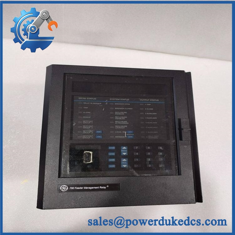
GE 760-P1-G1-S1-LO-A20-R
Application Scenarios & Pain Points
A feeder trip occurs during a process outage, yet the upstream protection system remains available. The 760 can provide feeder protection, metering, control, and event information, allowing the maintenance team to inspect the relay’s recorded operating data instead of relying solely on external indications.
Within industrial distribution systems, the 1 A CT configuration is the first electrical compatibility checkpoint. P1, G1, and S1 all specify 1 A inputs, so a visually identical 5 A configuration is not a direct electrical substitute.
For substations and plant feeder panels, the eight 4–20 mA analog outputs can transmit selected measurements or calculated values to external instrumentation and control systems. The receiving system must be configured for the same signal range.
During feeder automation work, the 760 platform’s automatic-reclosing capability may be part of the protection scheme. Reclosing settings must be transferred carefully because they can affect breaker operation and coordination with upstream protection.
At 50°C+ cabinet temperatures, thermal conditions should be checked before commissioning a replacement. The documented operating range extends to 60°C, while actual cabinet temperature depends on enclosure loading, ventilation, and neighboring heat sources.
🚨 Common Error Codes & Diagnostic Symptoms
The 750/760 documentation relies on relay diagnostics, self-test information, alarms, trips, and system status rather than a single universal numerical fault-code list. The following are therefore diagnostic symptoms, not unsupported GE error codes.
Symptom/Code: SELF-TEST / SERVICE indication → Diagnosis: The relay may have detected an internal diagnostic condition, or it may be in a service/test state; external control power and configuration must be checked first → Action: Review the diagnostic information and replace the relay only after an internal hardware fault is confirmed.
Symptom/Code: Breaker status does not agree with the physical breaker position → Diagnosis: Incorrect auxiliary-contact wiring, configuration, input circuitry, or relay logic may be involved → Action: Verify breaker contacts and input wiring, then replace the relay if the fault follows the unit.
Symptom/Code: Eight analog channels fail or remain outside their expected 4–20 mA range → Diagnosis: Check loop wiring, receiving-device loading, configuration, and common relay circuitry before identifying an internal analog-output fault → Action: Perform controlled loop testing; replace the relay when the fault is demonstrated internally.
🚨 Cross-Reference & Lifecycle Migration
Configuration Cross-Reference
The exact order code should be read as:
760 / P1 / G1 / S1 / LO / A20 / R
- 760: Feeder Management Relay with automatic reclosing
- P1: 1 A phase-current inputs
- G1: 1 A zero-sequence-current inputs
- S1: 1 A sensitive-ground-current input
- LO: 20–60 VDC or 20–48 VAC at 48–62 Hz
- A20: Eight 4–20 mA analog outputs
- R: Red breaker-closed LED
The 760-P1-G1-S1-LO-A10-R is a related configuration with eight 0–10 mA outputs rather than 4–20 mA, so it should not be treated as the same analog-output configuration.
Firmware Compatibility
The 750/760 platform uses field-upgradeable firmware. GE’s documentation distinguishes multiple firmware generations, and the installed firmware version can affect available functions and communications behavior. The actual relay firmware should therefore be recorded before replacement rather than assuming that two relays with the same base family have identical software.
For a maintenance replacement, compare the installed unit’s firmware revision, hardware revision, CT configuration, control-power class, analog-output range, communication options, and protection settings.
Lifecycle Status
Lifecycle: Legacy / Manufacturing Discontinued.
GE currently lists the 750/760 family among its legacy distribution products and states that manufacturing has been discontinued.
For an installed 760 population, this supports a controlled buffer-stock approach: retain exact configured spares for critical feeders, document firmware and protection settings, and maintain migration records for eventual replacement with a current feeder-protection platform.
Field Engineer’s Tech Notes
First warning: verify the LO supply before energizing the relay. This order code specifies 20–60 VDC or 20–48 VAC, not the high-voltage control-power range used by HI variants. Applying the wrong supply class can damage the equipment.
Second warning: verify CT secondary current before connecting the relay. P1, G1, and S1 are all 1 A configurations. Do not assume that the feeder’s existing CTs can be connected to any 760 relay merely because the enclosure and terminal arrangement match.
The drawout mechanism is another point worth checking. Inspect the rear connector and case alignment before insertion; a damaged drawout connector can create intermittent signals that resemble a relay electronics fault.
Strict QA & Testing SOP
1. Inbound identity verification
Confirm the complete 760-P1-G1-S1-LO-A20-R ordering code from the physical nameplate. Record serial number, hardware revision, firmware revision, and manufacturing/date information.
2. Mechanical inspection
Inspect the drawout case, front display, keypad, LED indicators, rear connectors, terminal points, guide hardware, and mounting surfaces for cracks, corrosion, contamination, or previous repair.
3. Configuration audit
Verify P1, G1, S1, LO, A20, and R against the purchase specification. A generic “760” label is insufficient for controlled inventory.
4. Power-up verification
Apply a controlled source within the verified LO range. Confirm normal startup, display operation, status indication, and self-test behavior.
5. CT-input simulation
Inject calibrated current appropriate to the 1 A phase, 1 A zero-sequence, and 1 A sensitive-ground inputs. Check phase identification, metering, and configured measurement values.
6. Analog-output verification
Exercise all eight 4–20 mA channels and measure loop current at representative points across the range. Confirm output assignment and scaling.
7. Digital-input/output verification
Simulate breaker auxiliary contacts, control inputs, and applicable relay outputs. Confirm status indication and programmed logic.
8. Communications test
Test the RS-232/RS-485 interfaces where applicable. Verify address, baud rate, parity, protocol response, and communication stability.
9. Protection-function test
Use the customer’s approved protection settings or study. Exercise applicable feeder protection, ground protection, breaker-failure, voltage/frequency, reclosing, and other enabled elements.
10. Event and recording test
Generate controlled test events and verify event recording, timestamps, waveform capture, and data logging where configured.
11. Final packaging
After passing inspection, place the relay in ESD-safe protection, secure the drawout mechanism, add impact cushioning, and retain all QC records with the serialized asset.
Test videos are available when live functional verification is performed and visual evidence is required.
Buyer’s FAQ
Is this exact 760 relay compatible with a 5 A CT system?
No. The P1/G1/S1 configuration specifies 1 A phase, zero-sequence, and sensitive-ground current inputs. A 5 A configuration uses different order-code selections and should be sourced accordingly.
Can the drawout relay be hot-swapped?
The drawout construction makes removal easier, but it should not be interpreted as unrestricted energized replacement. Feeder CT circuits, breaker-control circuits, and low-voltage power circuits must be handled according to the approved GE procedure and site electrical-safety requirements.
How do I verify a New Original unit?
Request photographs of the actual relay showing the complete 760-P1-G1-S1-LO-A20-R nameplate, serial number, hardware revision, display, rear terminals, and packaging. For a legacy protection relay, the exact ordering code is the primary identity check.
What warranty should be recorded?
The purchase document should state New Original, New Surplus, or refurbished condition, the warranty duration, serial-number coverage, functional-test scope, and applicable return conditions.
One secondary commercial record lists Canada as the manufacturing country and 85364900 as its tariff reference for this configuration. Those are transaction-specific commercial data, not universal classifications; verify the actual shipment’s COO and tariff code with current customs documentation before declaration.











 Start Chat


