

Description
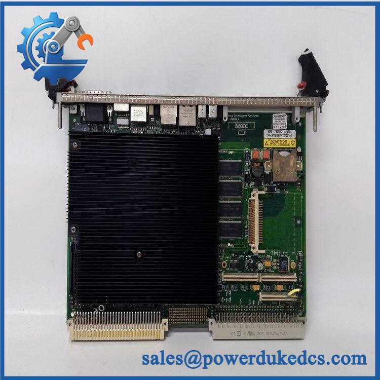
- Model: GE 7807RC / VME-7807RC
- Brand: GE Fanuc Embedded Systems
- Series: VMIVME-7807 / VME-7807RC
- Part Type: VMEbus Single-Board Computer (SBC)
- Core Function: Provides Pentium M-based processing, VMEbus control, storage, networking, serial communications, video, and embedded-system I/O from a single 6U VME slot.
- Key Specs: Intel 855GME chipset; Pentium M processor; up to 1.5 GB DDR SDRAM in the documented standard architecture; VME64; dual Gigabit Ethernet; four serial ports; four USB 2.0 ports; PMC expansion; passive cooling.
Product Introduction
When a legacy VME chassis reaches the point where its system controller can no longer be sourced, the motherboard is often the real obsolescence constraint. Replacing the entire VME architecture is rarely a simple maintenance task because application software, I/O maps, rear-transition modules, storage devices, and operating-system images may all depend on the original SBC.
The GE VME-7807RC is a single-slot, passively cooled 6U VMEbus computer based on the Intel Pentium M platform and Intel 855GME chipset. The documented architecture supports a 200-pin DDR SDRAM SODIMM together with optional 512 MB soldered memory for a maximum of 1.5 GB RAM; dual Gigabit Ethernet, SATA/IDE storage, serial interfaces, USB, video, and a PMC expansion site are also available.
Core Technical Specifications
| Parameter | Value |
|---|---|
| Manufacturer | GE Fanuc Embedded Systems |
| Product Family | VMIVME-7807 / VME-7807RC |
| Exact Model | VME-7807RC |
| Product Type | VMEbus Single-Board Computer |
| Form Factor | 6U VME Eurocard, single slot |
| Cooling | Passive cooling |
| Processor | Intel Pentium M |
| Chipset | Intel 855GME |
| System Memory | 1 GB DDR SDRAM standard configuration; optional 512 MB soldered memory |
| Maximum Documented RAM | 1.5 GB |
| Memory Socket | 1 × 200-pin DDR SDRAM SODIMM |
| VME Interface | VME64 |
| VME Transfer Modes | A32/A24, D32/D08, MBLT64, BLT32 |
| Front Ethernet | 1 × 10/100 Ethernet |
| Gigabit Ethernet | 2 × Gigabit Ethernet controllers |
| Serial Ports | 4 × 16550-compatible ports |
| Serial Configuration | Front-panel COM1; COM2/COM3/COM4 via rear I/O |
| Serial Modes | RS-232 / RS-422 configurable |
| Maximum Serial Rate | Up to 115.2 Kbaud |
| USB | 4 × USB 2.0, two front and two rear |
| Video | Integrated SVGA; rear DVI-D dual-head capability |
| Storage | Serial ATA / Ultra ATA; optional CompactFlash |
| IDE | Ultra ATA/100 support |
| PMC | 1 × 5 V PMC expansion site, PCI-X 66 MHz |
| Nonvolatile RAM | 32 KB |
| Watchdog | Software-selectable watchdog with interrupt/reset |
| RTC | Real-time clock/calendar |
| Keyboard/Mouse | PS/2 interface |
| VME Slot Occupancy | 1 slot |
| Board Height | 233.4 mm |
| Board Depth | 160 mm |
| Board Thickness | 20.3 mm |
| Approx. Weight | Approximately 1.2 lb / 0.54 kg for one documented configuration |
| Power — +5 V | 4.0 A typical / 5.4 A maximum |
| Power — +12 V | <1 mA |
| Power — -12 V | <1 mA |
| Operating System Support | Windows XP/2000, Linux, VxWorks, QNX, Solaris and other supported environments |
| Lifecycle | Legacy / discontinued |
The original GE Fanuc documentation specifies the 6U single-slot dimensions of 9.2 × 6.3 × 0.8 inches, the VME64 interface, four 16550-compatible serial ports, the 1.5 GB maximum memory configuration, and the +5 V requirement of 4.0 A typical / 5.4 A maximum.
The 1.5 GB memory ceiling requires the optional 512 MB soldered memory plus the SODIMM configuration; a bare SODIMM installation should not be represented as automatically providing the full 1.5 GB capacity.
Power and Thermal Note
For a standard VME chassis power-budget calculation, use the published +5 V, 4.0 A typical / 5.4 A maximum demand. That represents approximately 20 W typical and 27 W maximum at the 5 V rail, before considering PMC loading or other system-specific conditions.
The RC configuration is passively cooled, so chassis airflow and adjacent-slot thermal conditions remain important. Do not treat passive cooling as equivalent to zero thermal output.
GE 7807RC
Application Scenarios & Pain Points
A legacy simulation or instrumentation chassis starts producing intermittent processor resets. Before replacing the VME backplane, inspect the SBC’s 5 V supply, board seating, memory, storage media, and watchdog configuration. The VME-7807RC relies heavily on the chassis power environment, with a published maximum +5 V demand of 5.4 A.
In industrial process-control equipment, the board can serve as the embedded computing platform for software that needs access to VMEbus data alongside Ethernet and serial interfaces. Its single-slot architecture leaves the remaining chassis positions available for specialized VME I/O and PMC hardware.
For data-acquisition systems, the combination of VME64, Gigabit Ethernet, SATA/IDE storage, serial ports, USB 2.0, and optional CompactFlash provides several paths for moving and retaining collected data. Rear I/O is available for serial, video, storage, and USB functions through compatible rear-transition modules.
During legacy software migration, operating-system compatibility can become more important than raw processor performance. The documented platform supports environments including Windows XP/2000, Linux, VxWorks, Solaris, and QNX, so preserving the original software image can simplify a controlled replacement.
At elevated chassis temperatures, passive cooling requires careful attention to surrounding boards and airflow. A 50°C+ chassis environment should trigger a review of adjacent-slot loading and card-guide airflow before commissioning a replacement.
🚨 Common Error Codes & Diagnostic Symptoms
The is a computer board rather than a PLC I/O module, so there is no universal process-control fault-code list. Diagnostics normally appear through BIOS/POST messages, operating-system failures, watchdog events, or VME/application-level errors.
Symptom/Code: POST memory error / repeated memory detection failure → Diagnosis: The SODIMM or onboard memory configuration may be incompatible, defective, or poorly seated. The documented memory architecture uses one 200-pin DDR SODIMM with optional soldered 512 MB. → Action: Reseat or replace the memory using the approved configuration, then rerun POST diagnostics.
Symptom/Code: Watchdog reset / unexpected board restart → Diagnosis: The software-selectable watchdog can trigger a reset when the application fails to service the watchdog within the programmed interval. → Action: Determine whether the reset originates from application software, operating-system lockup, memory/storage failure, or hardware instability before replacing the SBC.
Symptom/Code: VMEbus access failure / application cannot communicate with VME devices → Diagnosis: Possible causes include incorrect VME address mapping, bus configuration, backplane faults, PCI-to-VME bridge problems, or application-driver issues. → Action: Verify the VME64 configuration and software mapping before replacing the processor board.
🚨 Cross-Reference & Lifecycle Migration
The VMIVME-7807 and VME-7807RC belong to the same Pentium M / 855GME generation, but the RC designation should not be treated as a generic replacement label for every VMIVME-7807 configuration. GE documentation explicitly presents the two as related products while ordering information allows processor speed and memory/CompactFlash selections.
Documented related identifiers include:
- VMIVME-7807
- Configuration-specific part numbers such as , , and .
- GE/VMIC assembly numbers in the 350-93007807-xxxxx range.;
These configuration numbers can specify different processor, memory, storage, or I/O arrangements. Therefore, without the complete configuration suffix is not enough to establish direct interchangeability.
Firmware and operating system: Firmware is not the only migration variable. BIOS, LAN-boot firmware, operating-system image, device drivers, CompactFlash/IDE contents, and application software can all affect whether a replacement boots and executes the original application.
The manual also notes that the VME-7807/7807RC can execute Windows XP, Windows 2000, Linux, VxWorks, Solaris, and QNX.
Lifecycle status: Legacy / discontinued. Current specialist inventory still exists, including new-old-stock, unused, and refurbished configurations. Current listings explicitly identify particular configurations as discontinued by the manufacturer.
For buffer stock, record the complete configuration number, processor speed, RAM, CompactFlash/storage configuration, BIOS revision, operating-system image, and rear-I/O module pairing.
Field Engineer’s Tech Notes
Warning 1 — Verify the chassis power margin before inserting the board.
The published requirement reaches 5.4 A at +5 V for the board. Add the PMC site and other VME cards before determining whether the chassis supply is adequate; a marginal 5 V rail can look like a processor failure.
Warning 2 — Do not assume every 7807RC has the same rear-I/O arrangement.
The rear interfaces rely on compatible rear-transition modules such as the documented VMIACC-0586/ACC-0586RC and VMIACC-0590/ACC-0590RC families. Check the actual RTM and its pinout before reconnecting field or system wiring.
Strict QA & Testing SOP
Step 1 — Exact identity inspection
Record , full configuration suffix, assembly number, serial number, processor designation, memory configuration, and CompactFlash/storage option.
Step 2 — Physical inspection
Check the front panel, VME connectors, card ejectors, PMC site, memory socket, CompactFlash interface, SATA/IDE connections, and rear-I/O interfaces.
Step 3 — Connector inspection
Inspect the VME P1/P2 connector area for contamination, bent contacts, corrosion, or damaged guide hardware. Never force the card into the chassis.
Step 4 — Memory inspection
Verify the SODIMM type and installed capacity. Where the optional soldered memory is present, document it before changing the SODIMM configuration.
Step 5 — Power verification
Use a protected laboratory VME chassis and verify the +5 V rail before insertion. Monitor current during startup against the documented electrical requirement.
Step 6 — POST/BIOS test
Boot the board with a controlled configuration. Record processor recognition, memory detection, BIOS status, storage detection, and any POST diagnostics.
Step 7 — Network test
Verify the front 10/100 interface and dual Gigabit Ethernet interfaces where installed. Check link negotiation and sustained data transfer.
Step 8 — Serial-port test
Test COM1 and the rear COM2/COM3/COM4 interfaces using suitable loopback or serial test equipment. Verify RS-232/RS-422 configuration where applicable.
Step 9 — USB and video test
Check USB 2.0 interfaces and SVGA/DVI-D video outputs. For dual-head operation, use the relevant rear-I/O hardware and documented configuration.
Step 10 — VMEbus test
Install the SBC with a known-good VME test card. Verify address access, interrupt behavior, DMA or block-transfer functions where applicable, and stable VMEbus operation.
Step 11 — Storage and OS test
Boot the intended operating-system image from the installed storage device. Verify drivers, application startup, Ethernet configuration, and required VME hardware access.
Step 12 — Watchdog test
Enable the watchdog only under controlled conditions and confirm the programmed interrupt/reset behavior. Record the configuration before returning the board to stock.
Step 13 — Thermal test
Run the SBC under representative processor, Ethernet, storage, and VME load while monitoring chassis and board temperature. Passive cooling makes this test important.
Step 14 — Final preservation
Back up the tested OS/application image where authorized, document BIOS and firmware revisions, protect the VME connectors with suitable packaging, and place the board in ESD-safe packaging.
Test videos are available for qualifying inventory when pre-shipment inspection evidence is required.
Buyer’s FAQ
Q1. Can I hot-swap the ?
Do not assume hot insertion is permitted. The board draws substantial current from the +5 V VME rail and connects simultaneously to VMEbus signals, rear I/O, PMC hardware, and chassis power. Use the chassis manufacturer’s approved insertion procedure; for routine maintenance, power down the VME system unless an expressly approved live-insertion architecture exists.
Q2. How do I verify a New Original 7807RC?
Ask for photographs of the actual board, including the full configuration number, assembly number, serial label, processor/memory markings, VME connectors, and PMC area.
This is especially important because the family was sold in multiple configurations, and current specialist inventories include several distinct suffixes.
Q3. What warranty should be specified?
For legacy VME computer boards, warranty is normally supplier-specific and depends on whether the unit is unused, surplus, or refurbished. Current listings show different commercial conditions even within the family.
The purchase order should state the exact condition, test status, warranty period, and return terms.
Q4. Does the include the latest firmware?
Do not assume it does. The platform includes BIOS and other low-level software components, and the operating system/application environment can also be highly configuration-specific. The original documentation supports several OS families, including Windows, Linux, VxWorks, Solaris, and QNX.
For replacement procurement, request the BIOS version, LAN-boot configuration, operating-system image, processor speed, RAM capacity, and storage configuration. These are much more useful compatibility fields than a generic statement such as “latest firmware.”
Lifecycle & Asset-Control Note
The is a legacy 6U VME Pentium M single-board computer. The documented hardware architecture provides up to 1.5 GB DDR SDRAM, VME64, dual Gigabit Ethernet, four serial ports, USB 2.0, video, storage interfaces, and a PMC expansion site.
For a long-running VME control or test system, preserve the complete configuration number and software image with the spare. A physically correct VME card without the correct BIOS memory, storage, rear-I/O arrangement, and operating environment may still fail the actual replacement test.











 Start Chat


