

Description
- Brand: GE
- Full Model Number: C-RS-401-00-0
- System/Series Family: GE Legacy Industrial Control Hardware
- Core Function: Application-specific control/relay assembly; exact function requires confirmation from the host system
- Top 3 Hardcore Specs: C-RS-401 configuration; RS-401 assembly designation; -00-0 revision/configuration suffix
- Assembly Type: Legacy industrial control component
- Interface: Application-dependent
- Power Requirements: Not reliably established from the model number alone
- Stock Status: New Surplus / Factory-Sealed or Fully Tested Refurbished subject to actual inventory condition
Module 3: Technical Product Introduction
For legacy GE equipment, a part number such as C-RS-401-00-0 should not be treated like a modern PLC catalog number. The designation identifies a specific configured assembly, but the model number alone does not provide enough reliable evidence to assign a definitive I/O count, communication protocol, operating voltage, or host-system family. For procurement, the priority is therefore an exact identification match against the original component, including its label, revision, connector arrangement, and the equipment in which it is installed.
That distinction becomes important when replacing obsolete control hardware. A visually similar GE board or relay assembly may use different circuitry, terminal assignments, or system interfaces. Before installation, compare the complete physical marking and applicable GE documentation. If the original equipment documentation is unavailable, a clear photograph of the label and PCB/assembly is the most reliable next step for establishing the exact technical specification.
Module 4: Application Scenarios & Field Realities
- During legacy equipment repair, the C-RS-401-00-0 should be matched directly against the failed component. Record every visible identifier before removal, including manufacturer markings, revision codes, connector labels, and any secondary assembly number.
- If the equipment has an intermittent relay or control fault, test the surrounding power and control circuitry first. A failed relay output can originate from an upstream driver, wiring problem, blown protection device, or unstable supply rather than from the C-RS-401 assembly itself.
- For critical spare inventory, an exact-match C-RS-401-00-0 is preferable to an undocumented substitute. Legacy control systems frequently depend on board-level wiring and circuit arrangements that are not apparent from the external connector geometry.
- When modernizing an obsolete GE installation, identify the complete control architecture before proposing migration. The existing C-RS-401-00-0 should be traced to its host cabinet, controller, relay circuitry, field wiring, and protection functions before selecting a modern replacement.
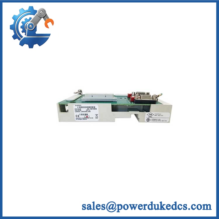
GE C-RS-401-00-0
Module 5: Migration, Compatibility & Installation Traps
Replacement Matrix
| Replacement Case | Classification | Engineering Requirement |
|---|---|---|
| C-RS-401-00-0 → identical C-RS-401-00-0 | Drop-in Replacement | Verify complete marking, revision, connector arrangement, and host-system compatibility |
| Same C-RS-401 family with a different suffix | Software/Configuration Verification | Confirm electrical and application compatibility |
| Different GE relay/control assembly | Hardware Modification Required | Validate wiring, voltage, contacts, mounting, and control logic |
| Unidentified substitute with similar appearance | Not Automatically Compatible | Obtain engineering documentation before installation |
Field Traps — Watch Out
1. Do not infer electrical ratings from the model number.
There is insufficient reliable public documentation from the designation C-RS-401-00-0 alone to establish its exact coil voltage, contact rating, I/O configuration, or communication characteristics. Those values must come from the original equipment documentation or the physical assembly identification.
2. Verify every connector before removal.
For a legacy control assembly, connector position and terminal assignment can be more important than the external dimensions. Photograph the installed wiring and label each connection before disconnecting the original unit.
Installation note: De-energize the host equipment according to the site’s electrical maintenance procedure. If relay contacts interface with high-energy circuits, verify isolation with the approved test instrument rather than relying on control-panel indicators.
Module 6: Quality Assurance SOP
For GE C-RS-401-00-0, the QA process should emphasize exact identification and application-specific functional testing because reliable public specifications for this designation are limited.
- Part-number verification: Confirm C-RS-401-00-0 on the physical assembly and purchasing record.
- OEM anti-counterfeit visual inspection: Examine GE markings, labels, assembly numbers, revision information, PCB construction, relay components, connectors, and manufacturing markings.
- Revision verification: Confirm the complete suffix -00-0 rather than accepting a generic RS-401 assembly.
- Mechanical inspection: Check mounting points, housing, PCB edges, connectors, terminals, and relay bodies for physical damage.
- Component inspection: Look for corrosion, overheated components, cracked housings, damaged terminals, and evidence of unauthorized repairs.
- Power-on self-test (POST): If a compatible GE test platform is available, energize the assembly using the documented supply voltage and monitor applicable status indications.
- Supply verification: Confirm the required input/supply voltage from the original equipment documentation before energizing. Do not apply an assumed voltage.
- Relay functional test: Where the assembly contains relay outputs, verify pickup/dropout behavior and contact continuity using controlled test conditions.
- Contact verification: Measure normally open and normally closed contacts independently and compare results with the applicable circuit documentation.
- Interface verification: Check all relevant input/output paths against the original cabinet schematic.
- Communication handshake verification: If the assembly is part of a communicating control system, verify the applicable system-level communication path.
- Final inspection: Recheck labels, terminals, connectors, mounting hardware, and packaging after testing.
- Traceability: Record the exact part number, visible revision, serial/manufacturing information where available, test setup, results, inspection date, and condition classification.
Procurement caution: I would not assign a specific voltage, protocol, I/O count, dimensions, or relay-contact rating to C-RS-401-00-0 without additional evidence. For this type of legacy GE component, the physical nameplate plus host-equipment information is necessary to produce a technically defensible specification.











 Start Chat


