

Description
- Model & Brand: GE Digital Energy D20C TERMINATION
- Legacy Part Number: 517-0169
- Current Smart Catalog Reference: D20CS-T-1
- Series: D20 / D200 Substation Automation
- Part Type: D20C LV Compression Termination / WESTERM Terminal Panel
- Physical Dimensions: The complete D20C assembly is approximately 19 × 5.25 × 2.5 in. (483 × 133 × 64 mm); the termination panel alone has no reliably published standalone envelope, so confirm the actual assembly before cabinet drawings.
- Estimated Shipping Weight: Approximately 2.7 kg / 6 lb based on distributor records for the 517-0169 panel; actual packed weight should control freight documents.
- What’s in the Box: D20C termination panel, compression terminal interfaces, DB25 interposer connection, ESD protection, and applicable QC documentation. Interposer relays, D20C WESDAC electronics, cables, and cabinet hardware are not assumed unless specifically included.
Product Introduction
The GE D20C TERMINATION is the physical field-wiring interface for the combination I/O peripheral. The legacy 517-0169 version is identified by GE as a WESTERM Type 1 Version 1 and corresponds to the newer D20CS-T-1 smart-catalog designation. Its job is straightforward but critical: land field status, control, and analog wiring on compression terminals while providing a DB25 interface for D20KI/KI2 interposer relays.
Mounted as part of the assembly, the termination panel sits between the field wiring and the active WESDAC electronics. It does not execute the RTU application itself. The exact variant must therefore be recorded with the termination board, because nearby D20CD, D20CB, D20CX, and D20CDI versions use materially different field-termination arrangements (important during brownfield replacement and audit reconciliation).
Core Technical Specifications
| Parameter | Value |
|---|---|
| Manufacturer | GE Digital Energy / General Electric |
| Product Name | TERMINATION |
| Legacy Part Number | 517-0169 |
| Current Smart Catalog | D20CS-T-1 |
| Legacy Description | WESTERM Type 1 Version 1 |
| Product Type | LV Compression Termination Board |
| Associated Platform | D20 / D200 Substation RTU |
| Associated I/O Module | Combination I/O Peripheral |
| Field Termination | Compression screw terminals |
| Interposer Interface | DB25 |
| Interposer Relay Compatibility | D20KI / D20KI2 |
| Intended Power Class | 20–60 VDC or D.20 power |
| Digital Inputs Supported by | 16 |
| Digital Outputs Supported by | 8 |
| Optional Analog Inputs | 16 with D20C1 daughterboard |
| Optional Analog Configuration | 8 AI + 8 AO with D20C2 daughterboard |
| Terminal Type | Board-mounted screw compression blocks |
| Maximum Field Wire Size | Approximately #12 AWG / 2.05 mm |
| Tool Specification | Approx. 0.6 × 3.5 × 100 mm blade screwdriver |
| Isolation, System | Approximately 1500 Vrms component isolation |
| Dielectric Rating | Approximately 1000 VDC |
| D.20 Link Ports | 2 on the complete WESDAC |
| Maintenance Port | RS-232, 9600 baud on complete WESDAC |
| Complete Power | 20–60 VDC |
| Typical Power | Approx. 5 W |
| Full-Load Power | Approx. 11 W with 24 V contact wetting |
| Complete Assembly Envelope | Approx. 19 × 5.25 × 2.5 in. |
| Termination Board Alone | Exact dimensions not reliably published |
| Processor on Termination Board | None |
| Memory | None |
| Standalone Firmware | None |
| Mounting | chassis / panel assembly |
| Hot Replacement | Do not assume live replacement |
| Lifecycle Position | Legacy / Order Book Closed |
Termination configuration
The 517-0169 / D20CS-T-1 arrangement is specifically the low-voltage compression termination with DB25 interface for interposer relays.
Do not substitute another termination simply because the connector count appears similar:
| Termination | Main Difference |
|---|---|
| D20CS-T-1 / 517-0169 | LV compression termination + DB25 for interposer relays |
| D20CS-T-2 / 517-0180 | DB25 termination |
| D20CS-T-3 / 517-0326 | Barrier termination + |
| D20CS-T-4 / 517-0217 | Compression disconnect + |
| D20CS-T-6 / 517-0333 | 48 V isolated-common configuration |
| D20CS-T-7 / 517-0263 | 130 V isolated-common configuration |
The termination choice directly affects field wiring, contact-wetting arrangements, and the mechanical interface to external interposer relays.
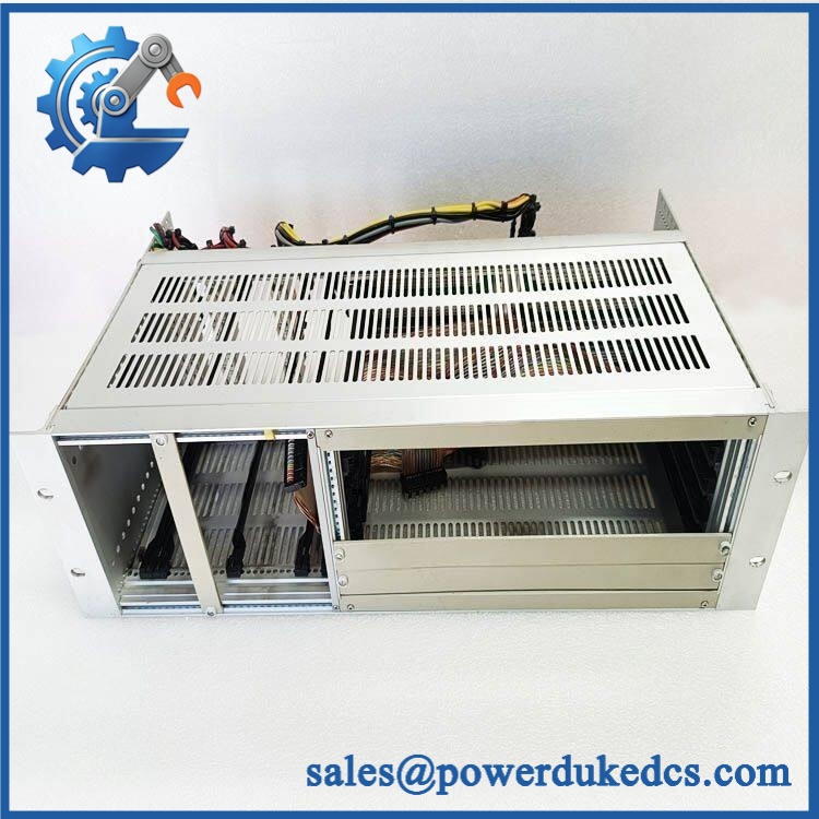
GE D20C TERMINATION
🚨 Global Compliance & Industry Certifications
The termination panel is part of the GE D20/D200 substation automation platform, so certification should be evaluated against the complete assembly and installed RTU rather than claimed independently for the terminal panel.
- CE Mark: Verify the applicable D20/D200 product declaration and the exact termination revision.
- UL/cUL: Confirm the complete /D20 RTU installation and applicable certification configuration.
- ATEX / IECEx: Do not assume hazardous-area certification for the standalone termination panel.
- Marine / DNV GL: No standalone marine approval should be assumed without project-specific documentation.
- Electrical Isolation: The platform documentation specifies approximately 1500 Vrms component isolation and 1000 VDC dielectric strength; these are electrical characteristics, not hazardous-area certifications.
- Country of Origin: Establish from actual manufacturing or traceability records.
- HS Tariff Classification: Confirm with the destination-country customs broker.
For substation work, certification boundaries matter because the terminal panel, WESDAC module, power supply, interposer relays, and cabinet may form one evaluated equipment configuration. A replacement terminal panel should not be represented as independently certified for every possible installation.
Verify specific lot certifications with OEM.
🚨 Long-Term Storage & Asset Preservation Guide
Keep the termination panel in an ESD-safe protective bag and protect the compression terminals and connector from dust and oxidation. Exposed terminal hardware is the first area I would inspect on an old shelf spare.
Store the panel in a clean, dry environment without condensation. For long-term inventory, target below approximately 60% RH where practical, particularly where exposed metal terminal surfaces and older connector materials are involved.
Do not tighten terminal screws repeatedly during warehouse inspection. Excessive mechanical cycling can damage the screw terminals without providing any useful preservation benefit.
Record 517-0169, D20CS-T-1, and the original configuration in the asset record. If the stored item is paired with a WESDAC board, preserve the complete assembly identity rather than separating the records.
Physical Installation Prerequisites
Install the TERMINATION only with the compatible WESDAC/peripheral architecture. The 517-0169 version is the low-voltage compression termination arrangement and includes the interface used with D20KI/KI2 interposer relays.
Field wiring can accommodate up to approximately #12 AWG / 2.05 mm conductors. Verify every terminal assignment against the original wiring documentation before disconnecting the existing panel.
The complete assembly operates from 20–60 VDC, while full-load system consumption can reach approximately 11 W when 24 V contact wetting is active. Those figures belong to the system rather than to the passive termination board itself.
Maintain the original panel mounting, grounding, cable segregation, and service access. The documented complete assembly is approximately 19 × 5.25 × 2.5 in., so the termination panel should not be evaluated as a small standalone PCB for enclosure-space purposes.
No universal 50 mm clearance rule should replace the actual D20 cabinet drawing. Preserve adequate room for terminal access, cabling, interposer-relay wiring, and ventilation.
Do not disconnect or install the termination assembly while energized unless the approved D20 maintenance procedure explicitly permits the operation.
Buyer’s FAQ — Logistics & Compliance Focus
Q: What HS Tariff Code should be used for TERMINATION?
A: The item is a specialized substation RTU termination panel, and the final Harmonized System classification depends on the importing country’s tariff schedule and customs interpretation. Identify the item as 517-0169 / termination panel in the commercial documentation and have the importer or customs broker confirm the final code.
Q: Does the export location establish Country of Origin?
A: No. COO should be supported by manufacturing or traceability documentation for the actual termination panel or production lot. Warehouse location and export port do not establish manufacturing origin.
Q: Does the TERMINATION include the latest firmware pre-loaded?
A: No. The termination panel is passive field-interface hardware with no processor, application memory, or standalone firmware. Software resides in the associated WESDAC/controller environment; the termination panel’s relevant identity is its physical terminal configuration and interposer interface.
Q: How should shipping insurance and physical packing be handled?
A: Insure the unit for its documented commercial replacement value and photograph the 517-0169 / marking, terminal blocks, connector, and mounting hardware before dispatch. Use an ESD-safe bag, rigid protection around the and terminal sections, moisture control, and internal cushioning; distributor records list approximately 6 lb / 2.7 kg for the 517-0169 panel, so actual packed weight should control the freight document.











 Start Chat


