

Description
- Model: GE DS200ADPBG1ABB
- Brand: GE / General Electric
- Series: Mark V DS200
- Part Type: Genius I/O Adapter Board
- Functional Acronym: ADPB
- Core Function: Provides the interface between the Mark V control architecture and associated Genius I/O hardware.
- Key Specs: One 8-position configuration switch block, one 40-pin connector, one 26-pin connector, and manually adjustable hardware jumpers. The board is identified as a Group 1 Mark V assembly with normal PCB coating.;
- Physical Reference: Approximately 159 × 178 mm in one secondary dimensional record; reported weight approximately 0.42 kg.
Product Introduction
The GE DS200ADPBG1ABB sits within the Mark V DS200 turbine-control architecture as a Genius I/O adapter board. Its role is interface-oriented: the board connects the Mark V electronics with Genius I/O equipment, while its configuration hardware determines how the installed assembly is used within the host system.
This is a legacy PCB, and its physical details deserve more attention than a generic product description suggests. The board carries an 8-position switch block, 40-pin and 26-pin connectors, and manually movable jumpers. Secondary parts documentation also identifies the unit as a normal assembly with normal PCB coating, Group 1, with A/B functional and artwork revisions represented in the full part number.Because historical documentation for this exact assembly is limited, the actual board markings should control replacement decisions.
Core Technical Specifications
| Parameter | Value |
|---|---|
| Manufacturer | GE / General Electric |
| Catalog Number | DS200ADPBG1ABB |
| Product Family | Mark V DS200 |
| Hardware Type | Genius I/O Adapter Board |
| Functional Acronym | ADPB |
| Mark V Grouping | Group 1 |
| Assembly Type | Normal Assembly |
| PCB Coating | Normal Coating |
| Reported Significant Revisions | 3 |
| Configuration Switches | 1 × 8-position switch block |
| 40-Pin Connector | 1 |
| 26-Pin Connector | 1 |
| Hardware Jumpers | Manually movable jumper links |
| Board Shape | L-shaped PCB assembly |
| Board Dimensions | Approx. 159 × 178 mm reported by secondary supplier |
| Reported Unit Weight | Approx. 0.42 kg |
| Estimated Shipping Weight | Approx. 0.8–1.2 kg with ESD packaging and cushioning |
| Operating Temperature | Exact OEM value not verified for this assembly |
| Storage Temperature | Exact OEM value not verified |
| Input Voltage | Exact board-level rating not verified |
| Power Consumption | Exact board-level rating not verified |
| Heat Dissipation | Exact board-level rating not verified |
| Standalone Firmware | No independently documented user firmware package identified |
| Mounting | Mark V DS200 cabinet/card assembly |
| Lifecycle | Legacy / Obsolete |
The 8-switch block, 40-pin connector, 26-pin connector, ADPB acronym, Group 1 designation, revision information, and normal coating classification are consistently identified in specialist Mark V parts records.;
The reported 159 × 178 mm dimensions and 0.42 kg weight should be regarded as logistics references rather than certified GE dimensional data.
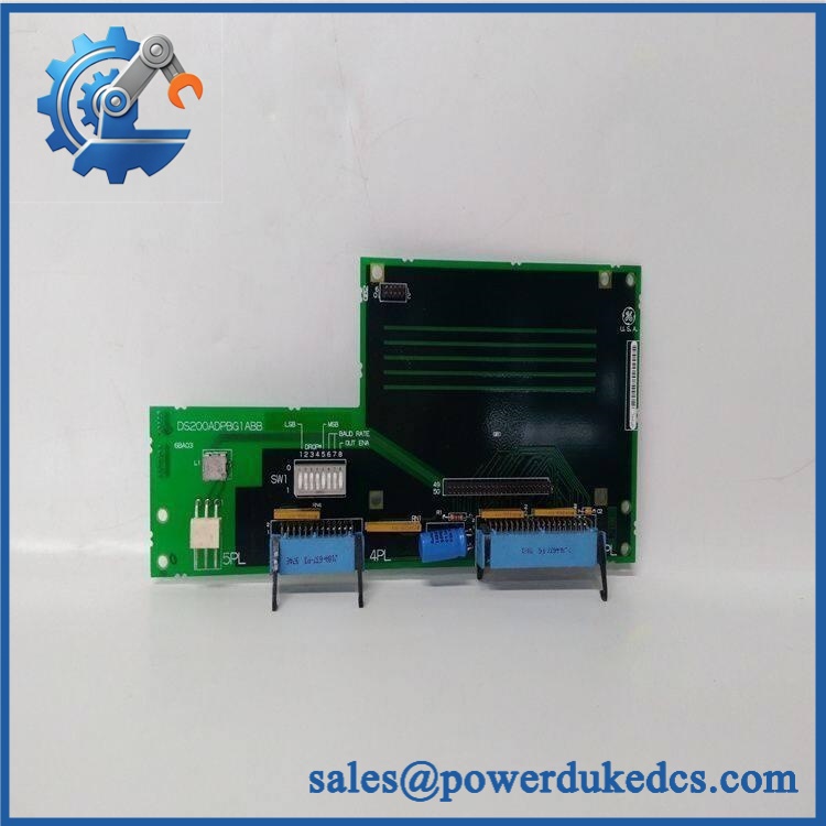
GE DS200ADPBG1ABB
Application Scenarios & Pain Points
Micro-case — Genius I/O communication fault: A Mark V turbine system continues to operate intermittently, but one group of Genius I/O points is no longer being exchanged correctly. After the Genius devices, wiring, and rack interfaces are checked, the ADPB adapter board becomes a possible failure point.
In legacy turbine installations, the DS200ADPBG1ABB provides the physical interface needed to integrate Genius I/O with the Mark V architecture. The board therefore has a system-level effect even though it does not function as a standalone CPU.
For maintenance teams supporting older generator or turbine-control cabinets, the 40-pin and 26-pin interfaces are important identity markers. A similar-looking DS200 board with a different functional acronym should not be inserted simply because the mounting geometry appears comparable.
When undocumented field modifications are present, the jumper configuration can become a maintenance issue. The board’s manually movable jumpers should be photographed before removal (especially on cabinets that have undergone previous retrofit work).
At 50°C+ cabinet temperatures, inspect connector solder joints, power-related components, and the board surface for thermal discoloration. An exact continuous operating-temperature specification for this exact assembly was not verified in the public documentation reviewed.
🚨 Common Error Codes & Diagnostic Symptoms
No authoritative GE service document located for DS200ADPBG1ABB establishes universal numerical fault codes. The following should therefore be treated as physical or system-level diagnostic symptoms.
Symptom/Code: Genius I/O points unavailable while the Mark V controller remains operational → Diagnosis: Possible Genius network, cable, terminal, adapter-board, or configuration fault; a failed ADPB can interrupt the interface path between the host controller and Genius I/O → Action: Verify Genius network wiring and configuration first, then substitute a known-good DS200ADPBG1ABB when the fault follows the board.
Symptom/Code: Intermittent I/O communication or data corruption → Diagnosis: Oxidized connectors, loose jumpers, board-level interface degradation, or intermittent solder joints can produce unstable communications → Action: Inspect the connectors and configuration hardware, then perform a controlled board substitution.
Symptom/Code: Configuration changes do not produce the expected Genius I/O behavior → Diagnosis: The 8-position switch block or hardware jumper configuration may not match the original installation → Action: Compare every switch and jumper position with the removed board and the approved Mark V configuration before replacing other system components.
🚨 Cross-Reference & Lifecycle Migration
Exact Part Identity
The controlled identity is:
GE — Mark V Genius I/O Adapter Board
The functional acronym is ADPB, and the board is identified as a Group 1 Mark V assembly.
Related GE products such as DS200ADPAG1A, DS200ADPAG1ABB, and DS200ADPBG1A are also identified as Genius adapter boards within the Mark V family. Similar naming does not establish a direct electrical replacement relationship.
Revision Control
The full suffix should be retained in the inventory record. Specialist documentation identifies three significant product revisions and notes that functional and artwork revisions can affect original specifications and dimensions.
Before approving a substitute, compare:
- Complete board number
- Functional revision
- Artwork revision
- Switch-block settings
- Jumper configuration
- 40-pin connector arrangement
- 26-pin connector arrangement
- Host Mark V cabinet position
Firmware Requirement
The ADPB is an interface board, not a modern programmable controller. No reliable independent firmware-flashing procedure was identified for this exact board.
Configuration is instead associated with the hardware switch block, jumper settings, and host Mark V system architecture. A replacement should reproduce the original hardware configuration rather than assuming a firmware update will resolve compatibility.
Lifecycle Status
Lifecycle: Legacy / Obsolete.
The DS200 Mark V product family is a mature turbine-control platform, and exact boards such as are now primarily handled through specialist spare-parts and repair channels.
For critical turbine assets, buffer stock should be tied to the exact board number and revision, not merely to the Genius adapter-board category.
Field Engineer’s Tech Notes
First warning: photograph the switch block and jumpers before touching the board. The ADPB contains an 8-position configuration switch block plus manually movable jumpers. Their original positions may be essential to the installed Mark V configuration.
Second warning: do not pull on the board by its connectors. The 40-pin and 26-pin connectors are mechanically stressed during extraction and insertion. Use the proper card-retention hardware and support the PCB by its edges (a damaged header can create intermittent Genius communication faults that are difficult to reproduce).
Use ESD protection throughout handling. Keep the board on an ESD-safe surface when it is outside the Mark V cabinet.
Strict QA & Testing SOP
1. Inbound identity verification
Confirm on the physical board. Record all GE labels, assembly numbers, revision markings, serial/date information, and packaging condition.
2. Physical inspection
Inspect the L-shaped PCB, connector housings, edge contacts, mounting holes, switch block, jumpers, solder joints, and component surfaces for mechanical or environmental damage.
3. Revision inspection
Record the functional and artwork revision information visible on the board. Do not assume all revisions have identical electrical characteristics.
4. Configuration documentation
Photograph all 8 switch positions and every jumper before applying power. Compare them with the customer’s original board.
5. Connector verification
Confirm the presence and condition of the 40-pin and 26-pin connectors. Check for bent pins, cracked plastic, oxidation, loose solder joints, or contamination.
6. Electrical pre-check
Perform controlled continuity and resistance checks on appropriate supply/interface paths according to the applicable Mark V service documentation. Do not use unverified third-party voltage values as acceptance limits.
7. Controlled system installation
Install the board in a compatible Mark V test assembly. Confirm correct seating, connector engagement, and mechanical retention.
8. Genius I/O communication test
Connect known-good Genius I/O equipment and verify the expected data exchange between the adapter board and the host system.
9. Configuration test
Confirm that the switch and jumper settings produce the expected Genius interface behavior. Test representative I/O points rather than relying only on LED status.
10. Fault-isolation test
Where permitted by the test procedure, introduce controlled communication interruptions and verify the expected system response.
11. Extended observation
Monitor the board under representative operating conditions for intermittent I/O loss, communication instability, abnormal heating, or configuration anomalies.
12. Final preservation
Place the approved PCB in ESD shielding packaging, protect both connectors, immobilize the switch/jumper area against impact, and attach the QC record.
Test videos are available when live-rig testing is performed and visual evidence is required for procurement approval.
Buyer’s FAQ
Is a PLC CPU?
No. It is identified as a Genius I/O Adapter Board in the Mark V family. Its primary role is interfacing Mark V control hardware with Genius I/O equipment.
Can I replace it with DS200ADPAG1ABB?
Do not assume direct interchangeability. Both are described as Genius adapter boards within the Mark V family, but their functional acronyms and board configurations differ. Compare the exact board numbers, revision data, connectors, switch settings, and the host cabinet documentation before substitution.
Can the board be hot-swapped?
Do not assume live replacement is permitted. The is part of a turbine-control system, and the host cabinet may contain hazardous electrical energy. Isolate and discharge the equipment according to the applicable GE Mark V maintenance procedure before removing the PCB.
How do I verify New Original authenticity and warranty?
Request photographs of the actual , including the GE label, full PCB, revision markings, 8-position switch block, 40-pin connector, 26-pin connector, jumper positions, and original packaging.
The purchase document should specify New Original, New Surplus, refurbished, or repaired condition, together with the functional-test scope and warranty period.
For long-term asset control, retain + functional acronym ADPB + Group 1 designation + hardware/artwork revision + switch settings + jumper configuration + host Mark V reference + COO + QC record + packaging condition as one controlled spare record.











 Start Chat


