

Description
- Model & Brand: GE General Electric DS200DCFBG1BGB
- Series: Mark V / 531X-family drive and excitation hardware
- Part Type: DCFB Power Supply & Feedback Board
- Compatible Applications: DC2000, CB2000, EX2000, FC2000, GF2000, ME2000, and AC2000 IGBT drive applications
- Physical Dimensions: Approximately 280 × 160 × 80 mm (W × H × D) based on supplier-listed packing/board-envelope data; verify the physical unit before final freight or cabinet documentation.
- Estimated Shipping Weight: Approximately 0.7 kg net for the board; final packed weight depends on ESD and shock protection.
- What’s in the Box: DS200DCFBG1BGB board, ESD shielding protection, rigid PCB support, and applicable QC documentation. Mating control boards, cables, SCR modules, and cabinet hardware are not assumed.
Product Introduction
The GE DS200DCFBG1BGB sits in the power-and-feedback layer of legacy GE DC2000, EX2000, and related drive systems. It receives control-power input from the control power transformer and generates the low-voltage rails required by downstream control electronics, while also processing voltage and current feedback signals used by the drive control architecture.
This is not a passive power-distribution card. The DCFB contains the +5 V, ±15 V, and ±24 V supply circuits, VCO feedback circuitry, line-voltage sensing, AC current-transformer interface functions, and SCR firing-control circuitry. The exact jumper and DIP-switch pattern is application-specific (critical when replacing a field board), and GE’s maintenance documentation requires the replacement board to retain the original configuration unless the procedure states otherwise.
Core Technical Specifications
| Parameter | Value |
|---|---|
| Manufacturer | GE General Electric |
| Model | DS200DCFBG1BGB |
| Board Family | DS200DCFB / DCFB |
| Series | GE Mark V / 531X drive architecture |
| Product Type | Power Supply & Feedback Board |
| Applications | DC2000, CB2000, EX2000, FC2000, GF2000, ME2000, AC2000 |
| Primary Input | 38 VAC ±10% from CPT |
| Alternative Input | 24 VDC from control power transformer, application dependent |
| Unregulated +24 VDC | 3 A |
| Unregulated -24 VDC | 1 A |
| Regulated +15 VDC | 0.8 A |
| Regulated -15 VDC | 0.8 A |
| External Load Available on ±15 VDC | 0.25 A each |
| Regulated +5 VDC | 4 A |
| Auxiliary AC Output | 115 VAC, application dependent |
| 115 VAC Fuse | 0.5 A, 2AG fast-acting |
| +24/+15/+5 V Fuse | FU2, 7 A, 2AG fast-acting |
| -24/-15 V Fuse | FU3, 7 A, 2AG fast-acting |
| VCO Nominal Frequency | 250 kHz |
| VCO Frequency Range | 0–500 kHz |
| VCO Feedback | AC line voltage, bridge voltage, shunt signals, and application-dependent motor voltage |
| ACCT Interface | AC line current transformer feedback |
| SCR Firing Function | Gate-array control and gate-pulse amplification |
| Configurable Jumpers | 12, with 13 on applicable later board revisions |
| DIP Switches | 7 |
| Red LEDs | 2 for FU2/FU3 fuse indication |
| Neon Indicator | 1 for FU1 fuse indication |
| Test Points | 5 |
| Plug Connectors | 18 |
| Stab Connectors | 9 |
| Processor | No general-purpose CPU |
| User Memory | None |
| Firmware | No standalone application firmware |
| Board Dimensions | Approx. 280 × 160 × 80 mm |
| Approx. Weight | 0.7 kg |
| Installation | Internal GE drive/excitation cabinet |
| Hot Replacement | Do not assume live replacement |
| Lifecycle Position | Obsolete / Legacy |
Power architecture
The DCFB receives 38 VAC ±10% from the control power transformer in the standard drive arrangement; the documentation also identifies 24 VDC for the applicable CPT configuration. Full-wave rectification creates the unregulated ±24 VDC rails, from which regulated ±15 VDC and +5 VDC are derived.
The documented ratings are substantial: +24 VDC at 3 A, -24 VDC at 1 A, ±15 VDC at 0.8 A each, and +5 VDC at 4 A. These outputs support other control boards and feedback circuitry, so a DCFB failure can appear elsewhere as multiple apparently unrelated control faults.
Revision and configuration control
The G1BGB board should be treated as a specific hardware/revision identity. The DCFB family contains multiple revision levels, and GE specifies 12 configurable jumpers plus seven DIP switches on the relevant board family.
Do not copy settings from a generic DCFB data sheet and assume they are correct for every machine. GE specifically instructs technicians to transfer the jumper and switch positions from the board being replaced, using the controller’s factory test-data sheet as the reference.
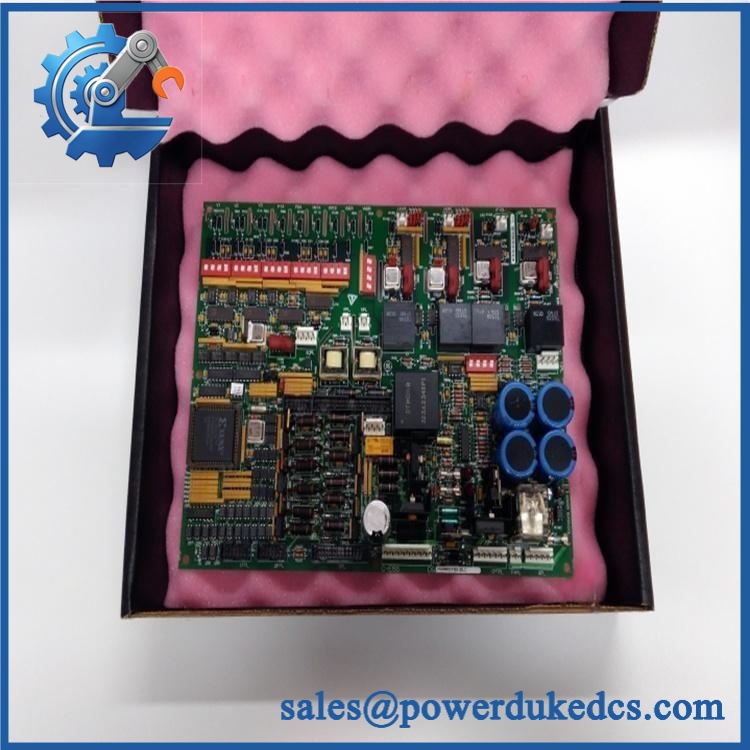
GE DS200DCFBG1BGB
🚨 Global Compliance & Industry Certifications
The DS200DCFBG1BGB is legacy industrial power/drive electronics. Certification should be evaluated against the complete GE drive, excitation, or control cabinet, not claimed independently for the PCB.
- CE Mark: Verify the applicable declaration for the complete GE equipment and production revision.
- UL/cUL: Confirm the certification covering the complete drive/excitation equipment rather than assuming standalone approval for the DCFB board.
- ATEX / IECEx: Do not assume hazardous-area certification for the bare DCFB board.
- Marine approvals: DNV GL or other marine certification should not be assumed without project-specific documentation.
- Electrical Safety: The board contains multiple energized DC rails, AC circuits, fuse-protected outputs, and high-energy components; maintenance requires proper isolation and discharge procedures.
- Country of Origin: Establish from actual manufacturing traceability or supplier documentation.
- HS Tariff Classification: Confirm the final classification with the destination-country customs broker.
The board’s 1500 V-class or similar isolation characteristics should not be confused with hazardous-area certification. For a drive cabinet, the certified equipment boundary controls where the complete assembly may be installed.
Verify specific lot certifications with OEM.
🚨 Long-Term Storage & Asset Preservation Guide
Keep the DS200DCFBG1BGB inside an ESD shielding bag and use rigid support around the board perimeter. The multiple plug connectors, stab terminals, and fuse holders should not be allowed to carry the mechanical load during storage or shipment.
This board contains substantial electrolytic-capacitor and power-conversion circuitry. For a spare that has remained on the shelf for years, inspect the capacitor bodies, fuse areas, transformer-related components, and solder joints before applying power. Do not use an arbitrary capacitor-reforming procedure; follow the approved GE service method for the specific revision.
Maintain a dry warehouse without condensation, preferably below approximately 60% RH for long-term inventory. Avoid corrosive vapors and large temperature changes around stored boards.
Preserve the 12 jumper settings and seven DIP-switch positions in the asset record. Photograph the board before storage and retain the machine’s original test-data sheet with the spare; that record can be decisive when the machine is out of service years later.
Physical Installation Prerequisites
Install the only in the specified GE drive or excitation cabinet and reproduce the original connector and mounting arrangement exactly.
Before energization, verify the correct control-power source. The documented DCFB input is 38 VAC ±10% from the CPT, with 24 VDC identified for the applicable CPT configuration. Do not substitute a generic external supply based on a reseller listing.
Check the output rails at the board test points during controlled commissioning:
- P5: regulated +5 VDC
- P15: regulated +15 VDC
- N15: regulated -15 VDC
- DCOM: common reference
- ACCT: AC current-transformer feedback test point
The fuse indicators provide useful first-line diagnostics. CR51 indicates FU2 trouble, CR55 indicates FU3 trouble, and LT1 indicates FU1 trouble. Persistent FU2 or FU3 failure with the designated connectors isolated is an explicit condition in GE’s troubleshooting procedure for replacing the DCFB board.
Maintain the cabinet’s original cooling path and service access. There is no defensible basis for assigning a universal 50 mm clearance to this legacy board; use the actual GE enclosure drawing.
Because the board may interface with high-energy drive circuits and SCR firing hardware, apply full lockout/tagout and discharge procedures before touching the board.
Do not remove or install the DCFB under power unless the exact GE maintenance procedure expressly permits the operation.
Buyer’s FAQ — Logistics & Compliance Focus
Q: What HS Tariff Code should be used for ?
A: The part is a specialized industrial drive power-and-feedback board, but the final Harmonized System classification depends on the importing country’s tariff schedule and customs interpretation. A supplier may propose a code under electrical control-board headings, but the importer or customs broker should confirm the final declaration.
Q: Does the shipping location establish Country of Origin?
A: No. COO should be supported by manufacturing or traceability documentation for the actual or its production lot. One aftermarket record identifies U.S. origin for the board family, but that should not replace unit-level documentation.
Q: Does include the latest firmware pre-loaded?
A: No standalone application firmware is involved in the normal sense. The DCFB contains gate-array logic and a serial-PROM-based gate-array programming function, but it is not a programmable Mark V CPU. The more important replacement controls are the correct hardware revision, jumper/DIP-switch settings, and compatibility with the associated SDCC/LDCC and PCCA boards.
Q: How should shipping insurance and physical handling be managed?
A: Insure the board for its documented commercial replacement value and photograph the complete marking, fuse positions, connectors, jumpers, DIP switches, and PCB condition before dispatch. Use an ESD shielding bag, rigid PCB support, moisture protection, and internal cushioning so the approximately 0.7 kg board cannot flex or shift during transportation.











 Start Chat


