

Description
- Brand: GE
- Full Model Number: DS200DCFBG2BNC
- Additional Marking: MRP569662
- Functional Acronym: DCFB
- System/Series Family: GE Mark V Speedtronic / DS200
- One-Sentence Core Function: DC power supply and feedback board providing regulated control power and feedback-supply outputs for Mark V drive/control hardware
- Top 3 Hardcore Specs: +24 VDC / 3 A; -24 VDC / 1 A; +5 VDC / 4 A
- Additional Outputs: ±15 VDC regulators; 115 VAC auxiliary output
- Stock Status: New Surplus / Fully Tested Refurbished subject to actual inventory inspection
Module 3: Commercial-Technical Deep Dive
A failed power-supply board can make a Mark V drive or turbine-control cabinet appear completely dead even when the processor and control cards remain functional. The GE DS200DCFBG2BNC, functional acronym DCFB, is a DC Power Supply and Feedback Board used in the GE Mark V DS200 architecture. Technical references identify the board as a revised DCFB assembly with 18 plug connectors and 9 stab connectors, seven DIP switches, twelve jumpers, five test points, and three protective fuses. The board receives approximately 38 VAC ±10% and derives multiple control and feedback supplies from that input.
The board’s output structure is the important service characteristic. The DCFB generates unregulated +24 VDC at 3 A and -24 VDC at 1 A, then derives ±15 VDC at 0.8 A each, with approximately 0.25 A available for external loading on each regulated ±15 V rail. It also produces +5 VDC at 4 A and supplies isolated +5 V and ±15 V rails for armature-current feedback circuits. The +5 V regulation state is monitored through the /PSEN signal, while fuse-protected power outputs use indicator circuitry to expose blown-fuse conditions. This makes the board a critical power-distribution element rather than merely a passive feedback interface.
Module 4: Compatibility & Installation Traps
Migration/Compatibility
- Replacement status: GE DS200DCFBG2BNC DCFB DC Power Supply and Feedback Board
- Logic rewrite: Not required. The DCFB is a power/feedback board, not a programmable controller.
- Firmware flash: Not applicable.
- Drop-in status: Potentially direct when the exact board revision, Mark V architecture, input voltage arrangement, DIP-switch settings, jumper configuration, and connected drive/control hardware match.
- Primary function: Converts incoming AC control power into multiple DC rails and supplies isolated feedback power.
- Board identification: The complete DS200DCFBG2BNC marking should be matched. MRP569662 should be retained as an additional identification/reference marking rather than substituted for the GE catalog number.
- Revision structure: Available documentation identifies the board as a Group 2 DCFB assembly with B-rated functional revision and N-rated secondary revision.
⚠️ Field Traps (Watch Out)
- DIP-switch configuration: The board contains seven DIP switches used for AC line-voltage selection and feedback-circuit voltage selection. Photograph and record every switch position before removing the original board.
- Fuse condition: Three fuses protect different power sections, with LEDs/neon indication associated with fuse status. A replacement that powers up but immediately loses a required rail requires circuit-level diagnosis rather than repeated fuse replacement.
- Input-power identification: The DCFB expects approximately 38 VAC ±10% from the associated power source according to available technical documentation. Do not apply a generic 24 VDC source directly to the board input.
- Feedback isolation: The board provides isolated supplies for armature-current feedback circuits. Wiring errors in these circuits can compromise drive feedback even when the main control power rails appear normal.
- High-voltage handling: The board contains AC-input and multiple energy-storage/power-conversion circuits. De-energize and verify the cabinet is safe before removal.
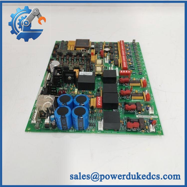
GE DS200DCFBG2BNC
Module 5: Quality Assurance SOP
Before shipment, the GE DS200DCFBG2BNC MRP569662 should undergo a dedicated power-supply-board inspection:
- OEM anti-counterfeit visual inspection — verify GE markings, DS200DCFBG2BNC identification, DCFB acronym, PCB artwork, connector arrangement, and board labels.
- Additional-marking verification — record MRP569662 exactly as shown on the unit and retain it as a traceability identifier.
- Mechanical inspection — examine all plug and stab connectors, mounting holes, heatsinks, transformers, terminal interfaces, and PCB surfaces for damage, corrosion, contamination, or unauthorized rework.
- DIP-switch and jumper inspection — photograph and document all seven DIP switches and twelve jumper positions before functional testing.
- Fuse inspection — verify fuse types, ratings, continuity, and physical condition before energization.
- Controlled AC input test — apply the specified input through a current-limited test setup and monitor board startup behavior.
- Power-rail verification — measure the applicable +24 V, -24 V, +15 V, -15 V, and +5 V outputs under controlled load conditions.
- /PSEN verification — verify that the +5 V supply status signal changes as expected between regulated and fault conditions.
- Feedback-supply verification — check the isolated supply outputs intended for armature-current feedback circuits.
- Test-point verification — use the designated test points to confirm representative voltage/reference conditions without exceeding board test limits.
- Load test — apply controlled loads to the specified output rails and monitor voltage stability and temperature behavior.
- Final QC record — document complete part number, MRP marking, DIP/jumper settings, fuse condition, measured rail voltages, test duration, photographs, and packaging condition.
For this DCFB board, a simple power-on check is inadequate. Every critical output rail, protection circuit, configuration switch, and feedback supply should be verified before release.
Module 6: CRO-Driven Buyer FAQ
1. Is GE obsolete, and how do I verify an authentic replacement?
The is legacy GE Mark V DS200 hardware, and current industrial references identify it as a DC Power Supply Board / DCFB assembly. The board is also documented as a revised version of the earlier DS200DCFBG2 design. For procurement, verify the complete marking, PCB revision, connectors, and the additional MRP569662 marking before accepting a replacement.
2. Can I hot-swap the ?
No. Treat the DCFB as energized power-conversion hardware. Isolate the cabinet, verify the absence of hazardous voltage, and follow the applicable Mark V maintenance and LOTO procedures before removal.
3. Does replacing the DCFB require reprogramming the Mark V controller?
No firmware or application rewrite is normally required. The DCFB does not contain the main control program. The critical commissioning work is electrical: restore the correct DIP-switch and jumper configuration, verify all required DC rails, and confirm the feedback supplies before returning the drive/control system to service.
4. What power outputs does the provide?
The DCFB architecture generates +24 VDC at 3 A, -24 VDC at 1 A, +15 VDC and -15 VDC at 0.8 A each, plus a +5 VDC output rated at 4 A. It also provides isolated +5 V and ±15 V supplies for armature-current feedback circuits and a 115 VAC auxiliary output protected by its own fuse.
5. What warranty and technical support are available?
Warranty duration should be stated according to the actual inventory condition, such as new surplus or tested refurbished. Technical support should cover exact board identification, MRP569662 traceability, DIP-switch and jumper verification, output-voltage testing, fuse inspection, and documented pre-shipment QA results. Live Mark V drive commissioning and high-energy electrical work remain the responsibility of qualified site personnel.











 Start Chat


