
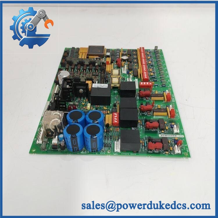

Description
The GE DS200DCFBG2BNC and DS200DCFBG1BNC are legacy DS200 DCFB Power Supply and Feedback Boards used in GE Mark V drive and excitation-control equipment. The board provides control-level power supplies while also handling voltage/current feedback, field-control circuitry, and electrical monitoring functions required by the host drive or excitation system. GE’s GEI-100028C documentation describes the DCFB as a power supply and instrumentation board with control-level +5 VDC, ±15 VDC, and ±24 VDC supplies.
Technical Specifications
| Specification | DS200DCFBG1BNC | DS200DCFBG2BNC |
|---|---|---|
| Brand | GE / General Electric | GE / General Electric |
| Series | Mark V DS200 | Mark V DS200 |
| Part Number | DS200DCFBG1BNC | DS200DCFBG2BNC |
| Functional Acronym | DCFB | DCFB |
| Product Type | DC Power Supply and Feedback Board | DC Power Supply and Feedback Board |
| Group | G1 | G2 |
| Functional Revision | B | B |
| Secondary Functional Revision | N | N |
| Artwork Revision | C | C |
| Primary Application | GE drive / excitation control | GE drive / excitation control |
| Associated Systems | DC2000, AC2000, CB2000, FC2000, ME2000, EX2000 | DC2000, AC2000, CB2000, FC2000, ME2000, EX2000 |
| Control-Level Outputs | +5 VDC, ±15 VDC, ±24 VDC | DCFB family function; verify exact group-specific ratings |
| +24 VDC Output | 3 A documented in GEI-100028C | Verify exact G2 configuration |
| −24 VDC Output | 1 A documented in GEI-100028C | Verify exact G2 configuration |
| +15 / −15 VDC Outputs | 0.8 A each | Verify exact G2 configuration |
| +5 VDC Output | 4 A | Verify exact G2 configuration |
| Auxiliary AC Output | 115 VAC output for connected equipment / cooling fan | Verify exact system wiring |
| Protection | 3 onboard fuses | 3 onboard fuses |
| Configuration Hardware | DIP switches and jumpers | DIP switches and jumpers |
| Diagnostic Hardware | LEDs / neon indicator and test points | LEDs / neon indicator and test points |
| Firmware | None on the DCFB board itself | None on the DCFB board itself |
| Weight Reference | Approx. 2 lb from secondary listing | Approx. 3.85 lb from secondary listing |
| Lifecycle | Legacy / discontinued | Legacy / discontinued |
The G1 electrical figures come directly from the GEI-100028C technical description. The G2-specific secondary listing identifies DS200DCFBG2BNC as a Group 2 DCFB board, with an approximate weight of 3.85 lb.
Functional Description
The DCFB board performs several functions within the host GE drive or excitation system:
- Generates control-level +5, ±15, and ±24 VDC supplies.
- Provides circuitry associated with motor field or generator excitation.
- Monitors AC-line voltage and current signals.
- Processes motor/bridge voltage and current feedback.
- Provides field-shunt and related instrumentation interfaces.
- Provides SCR gate-drive-related circuitry in applicable configurations.
- Supplies auxiliary AC power to connected cabinet equipment.
The GE manual describes the DCFB as receiving 38 VAC ±10% from the control power transformer in the documented configuration. The input is rectified and filtered to produce the unregulated ±24 VDC rails; regulators then derive the ±15 VDC supplies, while a separate regulator produces +5 VDC.
Feedback and Instrumentation
The DCFB is more than a power-distribution PCB. GE’s documentation shows dedicated circuitry for feedback and monitoring, including:
- AC line voltage
- AC line current
- Motor or generator field current
- Bridge or armature voltage/current feedback
- Field-shunt millivolt signals
- SCR-related control and feedback signals
The board communicates these signals with the associated SDCC/LDCC and SHVI/SHVM control hardware through multiple plug and stab connectors.
Configuration Hardware
The DCFB incorporates configurable hardware including DIP switches and jumpers. The GE documentation uses switch settings for functions such as AC-line and bridge-voltage scaling, while the exact jumper arrangement depends on the board/application.
This is an important replacement issue: the incoming board should not simply be installed with factory/default settings. The existing board’s jumper positions, DIP-switch positions, connector wiring, and host-drive configuration should be documented before removal.
Difference Between G1BNC and G2BNC
Although both boards belong to the DCFB family and use the same BNC revision suffix, the G1 and G2 designations represent different board groups.
The part-number structure is significant:
DS200 — GE DS200 Mark V board family
DCFB — DC Power Supply and Feedback functional acronym
G1 / G2 — board group
B — functional revision
N — secondary functional revision
C — artwork revision
The secondary-source documentation identifies DS200DCFBG2BNC as a Group 2 board and states that its revision history includes three board revisions.
Because G1 and G2 are different groups, one should not be described as an unconditional replacement for the other. The exact host equipment and board documentation should be checked before substitution.
Typical Applications
The DCFB family is associated with legacy GE:
- DC2000 drives
- AC2000 drives
- CB2000 drives
- FC2000 drives
- ME2000 drives
- EX2000 excitation systems
In EX2000 applications, the DCFB is part of the excitation-control signal and power architecture. GE documentation for the EX2000 identifies the DCFB as the board responsible for power distribution and instrumentation, including feedback signals passed through the SHVI/SHVM circuitry.
Replacement and Procurement Considerations
For an exact replacement, verify the following:
| Verification Item | Why It Matters |
|---|---|
| Complete part number | Distinguishes G1 from G2 |
| BNC suffix | Confirms the functional/secondary/artwork revision combination |
| Host drive or exciter | Determines the correct system application |
| Board revision | Hardware revisions may affect compatibility |
| DIP-switch settings | Affects signal scaling and configuration |
| Jumper settings | Application-specific configuration |
| Connector arrangement | Prevents wiring mismatch |
| Incoming control power | Must correspond to the installed system |
| SDCC/LDCC / SHVI/SHVM interfaces | Confirms system-level compatibility |
| Serial number / nameplate | Useful for exact spare-part identification |
GE’s manual explicitly states that the DCFB board contains application-specific configurable hardware and provides detailed connector tables for its interactions with NTB/3TB, SDCC/LDCC, SHVI/SHVM, and other system components.
Lifecycle and Obsolescence
Both DS200DCFBG1BNC and DS200DCFBG2BNC are legacy GE Mark V hardware. Current specialist suppliers continue to list the exact part numbers, but availability is primarily through legacy industrial automation inventory.
For a critical legacy drive or excitation system, the replacement should be sourced by the complete catalog number and hardware configuration, not by searching for a generic “DS200 DCFB board.”
Important Specification Note
The GEI-100028C documentation strongly supports the DCFB family function and the G1 electrical ratings quoted above. However, I did not find an OEM document that independently establishes every numerical specification for specifically. Therefore, G2-only values such as exact electrical ratings, dimensions, and weight should be confirmed against the installed board and applicable documentation before engineering use. The commonly published 3.85 lb G2 weight is a secondary-market reference.
FAQ
What is GE DS200DCFBG1BNC?
It is a GE Mark V DCFB DC Power Supply and Feedback Board, Group 1, used in legacy GE drive and excitation systems.
It is the Group 2 version of the DCFB DC Power Supply and Feedback Board used in the GE Mark V family.
Are DS200DCFBG1BNC and the same board?
No. They are related DCFB variants but have different G1 and G2 group designations. Direct interchangeability should be verified against the host equipment and board documentation.
What does DCFB mean?
It denotes the DC Power Supply and Feedback board function within the GE /Mark V architecture.
What DC supplies does the DCFB generate?
The GEI-100028C documentation describes +5 VDC, ±15 VDC, and ±24 VDC control-level supplies. The documented G1 board ratings include +24 VDC at 3 A, −24 VDC at 1 A, ±15 VDC at 0.8 A each, and +5 VDC at 4 A.
Does the board contain firmware?
The DCFB is a hardware power/feedback board rather than a firmware-bearing controller board. Its settings are primarily implemented through hardware components such as jumpers and DIP switches.
What manual covers the DCFB?
The relevant GE document is , DCFB Power Supply Board.
Can this board be used in Mark VI or Mark VIe?
Do not treat it as a Mark VI/Mark VIe replacement. The documented DCFB belongs to the legacy /Mark V architecture, with applications across GE legacy drive and EX2000 systems.











 Start Chat


