

Description
-
- Model & Brand: DS200DTBBG1ABB | GE General Electric
- Series: Mark V Speedtronic
- Part Type: Contact Input Expansion Termination Module
- Physical Dimensions: Approx. 11.5 × 3.0 in (292 × 76 mm) board envelope; populated assembly depth should be verified against the actual unit.
- Estimated Net Weight: Approx. 0.34–0.45 kg based on current industrial inventory records.
- Estimated Shipping Weight: Approx. 0.8–1.2 kg with ESD packaging and rigid carton
- What’s in the Box: DS200DTBBG1ABB board; ESD shielding bag; protective packaging; mounting hardware only when specifically included
- Terminal Blocks: 2
- Terminal Capacity: Up to 95 signal wires per terminal block according to published supplier specifications
- Primary Connectors: 3 × 50-pin connectors, designated JFF, JFG, JFH
- Additional Hardware: Bayonet connectors and 5 configurable jumpers
- Mounting: Four corner mounting holes
Product Introduction
A Mark V termination-board failure can become a wiring-management problem as quickly as it becomes an electronic problem. The GE DS200DTBBG1ABB is a Contact Input Expansion Termination Module used within the Mark V Speedtronic turbine-control system. Its two terminal blocks accommodate extensive field wiring, while three 50-pin connectors provide the interface to the control system. Five jumpers are available for configuration.
The board is approximately 11.5 inches long and 3 inches high and mounts through four corner holes inside the drive or control enclosure.It is a passive termination/interface assembly rather than a standalone processor, so firmware is not the principal lifecycle concern. Exact connector assignment, jumper position, and field-wire identification are far more important during replacement (especially after years of service in a turbine cabinet).
Core Technical Specifications
Parameter Value Manufacturer GE General Electric Part Number DS200DTBBG1ABB Series Mark V Speedtronic Product Type Contact Input Expansion Termination Module Functional Acronym DTBB Board Length Approx. 11.5 in / 292 mm Board Height Approx. 3.0 in / 76 mm Terminal Blocks 2 Terminal Capacity Up to 95 signal wires per block Primary Connectors 3 × 50-pin Connector IDs JFF, JFG, JFH Bayonet Connectors Included Configurable Jumpers 5 Mounting Holes 4 Application GE Mark V turbine-control system Interface Type Field contact termination and internal ribbon-cable interface Processor/Firmware None as a standalone board function PCB Family DS200 Lifecycle Discontinued / legacy spare Typical Installation Internal drive/control cabinet The three primary connector identifiers, two terminal blocks, five jumpers, and physical dimensions are consistently reported for the DS200DTBBG1ABB.
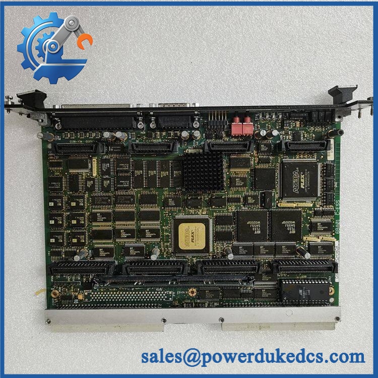
GE DS200DTBBG1ABB
🚨 Global Compliance & Industry Certifications
The DS200DTBBG1ABB is an internal component of the GE Mark V turbine-control platform. Certification should therefore be evaluated against the complete installed system and cabinet rather than assumed from the PCB itself.
- CE Mark: No standalone CE declaration specific to was established from the records reviewed.
- UL/cUL: No independent UL/cUL listing specific to this exact board was established.
- ATEX/IECEx: No standalone ATEX or IECEx certificate was established for .
- Marine Approvals: No board-specific DNV, ABS, or Lloyd’s Register approval was established.
- EMC: Installation quality remains relevant because the board carries extensive contact wiring and ribbon-cable interfaces.
- System Certification: Any hazardous-area or site-specific approval must be verified against the complete Mark V cabinet, field wiring, enclosure, and installed hardware configuration.
For hazardous-location assets, replacing a certified system component with a different board revision can create an audit issue even when the replacement physically fits. Verify specific lot certifications with OEM.
🚨 Long-Term Storage & Asset Preservation Guide
Keep the inside an ESD shielding bag during storage. The board contains capacitors, diodes, integrated circuits, connectors, and exposed electrical contacts; long-term exposure to dust, humidity, or uncontrolled handling can degrade the assembly without obvious visual damage.
Maintain a dry, stable warehouse environment. A practical preservation target is below 60% RH, with no condensation cycles. Before opening a cold package, allow the sealed ESD bag to reach ambient temperature to prevent moisture from forming on the PCB and connector surfaces.
Photograph and record the five jumper positions. The jumper configuration should be treated as part of the asset record along with the three connector assignments. The published board description confirms five jumpers and the JFF/JFG/JFH connector designations.
Protect the terminal blocks mechanically. Do not stack heavy equipment directly on the screw-terminal assemblies. Bent hardware or damaged terminal insulation can create field-wiring faults even when the PCB remains electrically intact.
Do not prescribe capacitor reforming without an approved procedure. No board-specific reforming interval was established in the reviewed documentation. A controlled electrical inspection and functional test before critical deployment is the more defensible release criterion.
Physical Installation Prerequisites
The is an internal Mark V termination board, not a DIN-rail assembly. It is attached through four corner mounting holes inside the drive/control enclosure.
Before installation:
- Confirm the host system is a GE Mark V Speedtronic installation.
- Verify the complete identification before removing the existing board.
- Photograph every connected ribbon cable and terminal wire.
- Match JFF, JFG, and JFH exactly. Do not rely on cable length or connector appearance.
- Record all five jumper positions before removal.
- Inspect the four mounting points and board-support hardware.
- Check every connector for bent, recessed, oxidized, or contaminated contacts.
- Keep power conductors separated from low-level signal and ribbon cables where the cabinet layout permits. Poor routing can introduce interference and impair cabinet airflow.
- Preserve the original cable-routing path after replacement.
- Verify cabinet grounding and shield connections against the approved Mark V drawings.
- Do not impose a generic 50 mm clearance around the PCB; use the actual Mark V cabinet ventilation arrangement.
- Use ESD controls throughout removal, inspection, and installation.
Buyer’s FAQ
Q1. What HS tariff code should be used for ?
A: Do not treat the product description as sufficient for final customs classification. Because this is a dedicated electrical termination/control component, HS heading 8538 may be considered where the importing country’s tariff schedule treats it as a part suitable for electrical control apparatus. The final country-specific code should be confirmed by the importer or customs broker.Q2. Does Country of Origin equal the country where my supplier ships the board?
A: No. COO concerns the applicable origin rules for the physical item, not the warehouse from which it departs. For an audit-ready record, retain the manufacturer’s origin evidence or supplier declaration, board identification, commercial invoice, and Certificate of Origin when required.Q3. How should this board be packed and insured for international shipment?
A: Place the PCB in an ESD shielding bag, protect the three ribbon-cable connectors and terminal blocks against impact, immobilize the assembly inside a rigid carton, and use moisture protection suitable for the route. Current industrial records report approximately 0.75 lb / 0.34 kg for one listing, while other suppliers report higher packed weights; use the actual packed weight for freight booking.For critical turbine spares, shipping insurance should cover the declared replacement value.Q4. Does include the latest firmware pre-loaded?
A: No. This board is a termination/interface assembly rather than a standalone processor. There is no conventional application firmware package to preload on the board. The important configuration records are the JFF/JFG/JFH cable assignments, five jumper settings, and associated Mark V system configuration.A: No, not as a routine maintenance procedure. The board is connected to extensive field wiring and internal ribbon cables. Isolate the relevant Mark V equipment according to the approved site procedure, document the wiring before removal, install the replacement, and perform continuity and functional checks before returning theturbine-control system to service.











 Start Chat


