

Description
- Model: DS200RT8AG3AHC
- Brand: General Electric (GE)
- Series: Mark V Speedtronic
- Part Type: RST Analog I/O Board / RT8A board
- Core Function: Conditions and scales analog and related field signals for the Mark V R/S/T control cores, including signals associated with turbine instrumentation, position feedback, and control outputs.
- Key Specs: G3 group, H coating style, A/H/C revision tail, 3PL COREBUS connection, JE interface to associated TCQC hardware, J1/J2/J5/J6 configuration jumpers, J7 test interface, and J8 oscillator-related configuration. The exact board is commonly identified in commercial records as an RST Analog I/O Board (TCQA).
Product Introduction
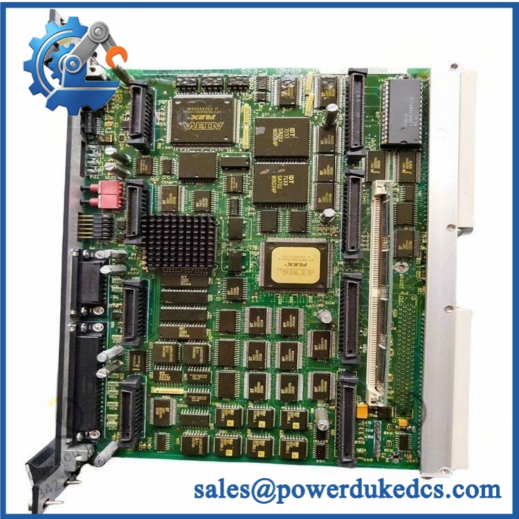
GE DS200RT8AG3AHC
The sits in the I/O signal-conditioning path and is identified as an RST analog I/O board, handling scaling and conditioning of signals associated with the R1, R2, and R3 cores. Public technical records associate the board with LVDT, thermocouple, 4–20 mA, vibration, pulse, and related turbine-control signals.
This board deserves strict revision and configuration control. The physical assembly uses the 3PL COREBUS connection for conditioned data transfer, a JE interface for related generator/line or TCQC-side signals, and several jumpers that affect particular circuit functions. The suffix AHC should therefore remain in the warehouse description rather than being shortened to DS200RT8AG3A (particularly during legacy Mark V migration).
Core Technical Specifications
| Parameter | Value |
|---|---|
| Manufacturer | General Electric (GE) |
| Part Number | |
| Functional Board Family | RT8A |
| Functional Description | RST Analog I/O Board |
| Related GE Description | TCQA analog I/O function |
| Product Family | Mark V Speedtronic |
| Mark V Core Association | R1 / R2 / R3 I/O cores |
| Group / Style Code | G3 |
| PCB Coating Code | H |
| Functional Revision 1 | A |
| Functional Revision 2 | H |
| Artwork Revision | C |
| Primary Data Connection | 3PL / COREBUS |
| Associated Interface | JE |
| Power Connection | 2PL from TCPS-related power architecture |
| Reported Analog Inputs | LVDT, thermocouple, 4–20 mA, vibration, pulse-related signals |
| Reported Analog/Control Outputs | Servo-valve, relay-driver, 4–20 mA related circuits |
| Configuration Jumpers | J1, J2, J5, J6, J7, J8 |
| J1/J2 Function | mA output-circuit configuration |
| J5/J6 Function | 20 mA / 200 mA range selection |
| J7 Function | RS-232 test interface / diagnostic use |
| J8 Function | Oscillator-related configuration/startup |
| Processor | No independent user CPU specification established |
| Application Memory | No independent user memory specification established |
| Firmware | No standalone application firmware specification established |
| Ethernet | No independent Ethernet interface established |
| Fieldbus | No independent fieldbus interface established |
| Power Dissipation | Exact board-level value not verified |
| Operating Temperature | Exact OEM value for this complete revision not verified |
| Storage Temperature | Exact OEM value not verified |
| Physical Dimensions | Exact OEM mechanical drawing not verified |
| Net Weight | Exact OEM net weight not verified |
| Lifecycle | Legacy / Obsolete Mark V hardware |
The available exact-model records consistently identify as an analog I/O board and document the 3PL, JE, 2PL, and jumper functions.
No sufficiently reliable source was located for the exact board’s certified dimensions, net weight, heat dissipation, or environmental rating. Those values should therefore be measured or confirmed from the original GE drawing before they are entered into a controlled asset database.
Application Scenarios & Pain Points
Micro-case — fuel-control feedback becomes unstable while the Mark V processor remains online. A problem on the analog conditioning path can produce abnormal process values or valve-position feedback even though the controller itself has not lost power. The RT8A board should be investigated only after terminal-board wiring, sensors, and external signal circuits have been checked.
For gas-turbine instrumentation, the board is associated with multiple analog signal types, including 4–20 mA process measurements, thermocouple inputs, vibration-related signals, and LVDT feedback. This makes channel-specific diagnosis important; one bad transmitter should not be mistaken for a board-wide failure.
Within R/S/T redundant control architectures, the board’s role is tied to the three Mark V control cores. Comparing the same signal across cores can help isolate a board-side fault from a common field-input problem (revision matching across the redundant set should also be checked).
At cabinet temperatures around 50°C, inspect connectors, terminal interfaces, capacitors, and solder joints carefully. The exact environmental rating for this complete AHC revision was not independently verified, so the original Mark V cabinet specification should remain authoritative.
🚨 Common Error Codes & Diagnostic Symptoms
The does not provide a modern standalone numerical diagnostic system. Fault isolation is normally based on Mark V alarms, core status, measured values, jumper configuration, and signal-path testing.
Symptom/Code: Analog value disagrees with field instrument → Diagnosis: Possible transmitter fault, terminal-board problem, incorrect scaling, jumper configuration, or RT8A analog-conditioning failure. → Action: Compare the field signal at the terminal board and board input/output path; replace the RT8A only after the external source is proven correct.
Symptom/Code: Servo-related position feedback becomes unstable → Diagnosis: Possible LVDT wiring issue, connector problem, signal-conditioning fault, or incorrect board configuration. → Action: Verify LVDT excitation and feedback wiring, inspect JE/3PL interfaces, and replace the board when the fault remains localized.
Symptom/Code: Multiple analog channels fail together → Diagnosis: A common power, COREBUS, connector, or board-interface problem is more likely than several independent field devices failing simultaneously. → Action: Check the 2PL supply path, 3PL connection, common circuitry, and board condition before replacing individual field instruments.
🚨 Cross-Reference & Lifecycle Migration
Cross-Reference
The strongest identification relationship is within the family. Current technical records identify the board as an RST Analog I/O Board (TCQA) and distinguish it from other RT8 variants.
Related parts such as DS200RT8AG2AHC and DS200RT8BG1A appear in the broader RT8 family, but the available evidence does not establish universal interchangeability. The G3 group, H coating, connector arrangement, and jumper configuration should be matched against the installed board before any substitution is approved.
Do not use a generic “TCQA” description as the engineering cross-reference.
Firmware Requirement
No conventional user firmware flashing has been established for the board itself.
The documented J7 interface is associated with board testing, while J











 Start Chat


