

Description
- Model & Brand: GE General Electric DS200SDCCG1AEC
- Series: Mark V / DS200
- Functional Description: Drive Control Card
- Functional Acronym: SDCC
- Hardware Group: G1
- Revision Identification: Functional Revision 1 = A; Functional Revision 2 = E; Artwork Revision = C. The complete suffix should be matched before replacement.
- Approx. W × H × D: Approximately 260 × 190 × 38 mm based on published distributor dimensions for this board family; verify against the actual packed unit before cabinet or freight planning. Published dimensional data is not presented as a GE mechanical drawing.
- Estimated Shipping Weight: Approximately 1.1 kg / 2.5 lb based on distributor data; packed gross weight can be higher.
- What’s in the Box: DS200SDCCG1AEC control card with protective anti-static packaging. Do not assume the original field configuration memory components are included unless specifically stated; GE documentation distinguishes the DS200 and DS215 implementations.
Product Introduction
The GE DS200SDCCG1AEC is the SDCC Drive Control Card used in the Mark V drive architecture. GE’s GEI-100029 documentation describes the SDCC as containing the primary control circuitry and software for a drive or exciter, with three 16-bit processors connected through dual-ported RAM. The three principal processors are the Drive Control Processor (DCP), Motor Control Processor (MCP), and Co-motor Processor (CMP). The DCP handles system-level functions and outer regulation loops, while the MCP handles inner motor-control functions; the CMP supplies additional calculation capacity where the application requires it.
This is a configuration-sensitive legacy board, not a generic PLC CPU. Connector assignments support power/interface boards, drive terminal boards, signal-processing boards, and the LAN Communications Card, while onboard jumpers determine application-specific hardware behavior. Ten diagnostic LEDs provide fault indications, and the same LED bank can also be configured to display certain drive variables. Because firmware, EEPROM parameters, jumper positions, and auxiliary boards can affect operation, the complete DS200SDCCG1AEC identity should be recorded before sourcing a replacement.
Core Technical Specifications
| Parameter | Value |
|---|---|
| Manufacturer | GE General Electric |
| Model | DS200SDCCG1AEC |
| Series | Mark V / DS200 |
| Functional Acronym | SDCC |
| Product Type | Drive Control Card |
| Primary Application Group | AC2000, DC2000, and EX2000 drive applications |
| Processor 1 | 80C186-based Drive Control Processor (DCP) |
| Processor 2 | 80C196-based Motor Control Processor (MCP) |
| Processor 3 | TMS320C25 Co-motor Processor (CMP) |
| Memory Architecture | Dual-ported RAM plus EPROM/EEPROM-based application/configuration storage |
| Factory Software Storage | Four EPROM devices are documented for the DS215 implementation; EEPROM U9 stores field-adjustable parameters |
| Main Control Interface | Drive and motor signal processing plus customer I/O |
| Connector Set | 1PL, 2PL, 3PL, 6PL, 7PL, 8PL, 9PL, 11PL on the SDCC architecture |
| LAN Interface | 3PL provides SDCC output to the associated LAN Communications Card |
| Terminal-Board Interfaces | 6PL and 8PL interface with NTB/3TB or STBA assemblies |
| Signal Processor Interface | 7PL interfaces with SPC/SPCB hardware where applicable |
| Meter Interface | 11PL provides SDCC outputs to meters |
| Diagnostic LEDs | 10 LEDs |
| Fault Display Range | Faults 1–399 use slow BCD-style indication; 400–1023 use faster binary-style indication |
| Testpoints | Multiple dedicated testpoints for supply rails, timing, analog feedback, and processor diagnostics |
| Configurable Hardware | Berg-type JP jumpers and wire jumpers |
| Reset Methods | RESET pushbutton, external +5 to +24 VDC reset, software reset, hardware watchdog reset |
| Power Supply Interface | SDCC power inputs include ±5, ±15, and ±24 VDC paths through the power/interface circuitry |
| Standalone Power Consumption | No reliable single-board wattage figure published in GEI-100029; system configuration determines actual demand |
| Heat Dissipation | No dependable standalone thermal figure published in GEI-100029 |
| Firmware / Software | Yes; processor software and programmable memory are integral to operation |
| Mounting | Mark V control/drive rack |
| PCB Coating | Normal coating |
| Static Sensitivity | Static-sensitive electronic assembly |
The OEM manual identifies the G1 group as the SDCC configuration used with AC2000, DC2000, and EX2000 applications. It also states that G4 versions use different firmware and enlarged EEPROM parameter storage, which is one reason a G1A-family replacement should not be substituted solely on the basis of the generic SDCC designation.
Revision and Memory Control
The DS200SDCCG1AEC has three identifying revision fields: A functional revision, E functional revision, and C artwork revision. Keep all three in the purchasing and asset records.
GEI-100029 also makes an important distinction between DS200 and DS215 boards. The document states that the DS200SDCC card is supplied without the five socketed memory chips, whereas the DS215 version is specified as the replacement format intended to include them. For an existing installation, verify the actual memory devices, application parameters, and board configuration rather than treating every SDCC board as electrically identical.
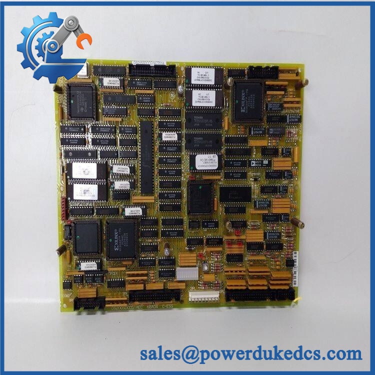
GE DS200SDCCG1AEC
🚨 Global Compliance & Industry Certifications
The available GEI-100029 documentation identifies the DS200SDCC family as an industrial drive-control board but does not establish a standalone CE, UL/cUL, ATEX/IECEx, or Marine/DNV GL certificate specifically for .
For compliance files, certification should therefore be evaluated at the applicable drive/system assembly level, using the original equipment certification package, nameplate markings, and installation documentation. A reseller statement that a board is “CE” or “UL” should not by itself be treated as evidence of a standalone certification for this exact revision.
For international shipment and audit records, retain the complete part number, revision data, serial/reference markings, condition description, inspection record, and documented country of origin.
Verify specific lot certifications with OEM.
🚨 Long-Term Storage & Asset Preservation Guide
- Store the in an ESD-safe protective bag and use rigid packaging that prevents the PCB from flexing or the connectors from being struck.
- Maintain a dry, stable storage environment and avoid condensation. For long-term warehouse storage, keep the board away from direct sunlight, dust, corrosive atmospheres, and repeated temperature swings.
- Protect the socketed memory devices, jumper headers, diagnostic LED area, and edge/plug connectors from contamination and physical contact.
- Record the exact G1 / A-E-C revision identity in the spare-parts database; a visually similar SDCC board can belong to another hardware group or firmware configuration.
- When a failed board is available, preserve its EPROM/EEPROM configuration relationship and jumper positions as part of the replacement record. GE documents U9 as the field-adjustable parameter memory, making configuration traceability relevant to recommissioning.
Physical Installation Prerequisites
Installation belongs within the appropriate Mark V drive/control rack, with the board connected to the associated power/interface, terminal, and optional signal-processing hardware defined by the application. It should not be treated as a standalone DIN-rail module.
Before handling the board, remove the relevant equipment power and follow the drive’s discharge and zero-voltage verification procedure. GE’s documentation begins with an electrical shock/burn warning and restricts installation and maintenance to adequately trained personnel. A hard SDCC reset can also trip the system, so reset functions should not be operated casually while equipment is running.
Jumper settings require special attention. GE documents JP1 for EEPROM parameter write protection, JP7/JP8 for feedback VCO functions, JP15/JP22/JP33 for processor crystal functions, and other jumpers for application-specific signal selection. Factory-set jumper positions are associated with controller test data, so compare the replacement against the installed configuration before energization.
Do not assume a universal cabinet-clearance value. Use the original Mark V mechanical arrangement for card access, connector engagement, cable routing, grounding, and service clearance.
Buyer’s FAQ — Logistics & Compliance Focus
Q: What HS Tariff Code should be used for ?
A: Published distributor data sometimes assigns industrial control boards in this category to HS 8538.90, but the correct tariff classification depends on the importing country’s tariff schedule and the precise customs description. Confirm the final code with your customs broker before entry.
Q: What should be listed as Country of Origin (COO)?
A: Use the origin shown on the supplier’s documented COO record or the product’s traceability documentation. Do not infer the COO from the current warehouse location.
Q: Should shipping insurance be included?
A: For a legacy control PCB with configuration-dependent electronics, insurance is appropriate to evaluate when the declared replacement value is material. Use ESD protection, impact-resistant packaging, and pre-shipment serial/condition records to strengthen a freight claim file when required.
Q: Does come with the latest firmware pre-loaded?
A: This should be verified for the specific unit. GEI-100029 identifies programmable memory and field-adjustable parameters as part of SDCC operation, and different SDCC hardware groups can use different firmware. Do not assume that a board with the same base SDCC designation contains the correct application image for your drive.
Replacement control point: For procurement, record exactly as marked. Do not shorten it to DS200SDCCG1A when the installed system requires the E functional revision and C artwork revision.











 Start Chat


