

Description
- Model: DS200SDCCG4AGD
- Brand: GE General Electric
- Series: Mark V Speedtronic
- Part Type: SDCC Drive Control Card
- Functional Acronym: SDCC
- Application: TC2000 turbine / drive control systems
- Board Revision: Functional A / G, Artwork D
- PCB Coating: Normal coating
- Approx. Dimensions: 12.5 × 6.5 × 1.5 in reported by secondary inventory records; verify actual dimensions before packing
- Estimated Shipping Weight: 0.8 kg / 1.76 lb reported by secondary inventory records; physically re-weigh packed material before freight booking
- Processor Architecture: 3 microprocessors with shared RAM
- Test Point: P15 = regulated +15 V supply
- Status Indicators: 10 LEDs arranged for startup, status, and error-code indication
- Memory: Shared RAM plus nonvolatile parameter/configuration memory; exact capacity is application/revision dependent
- What’s in the Box: DS200SDCCG4AGD board only unless the PO explicitly includes PROM/EEPROM devices, mounting hardware, or documentation
- Packaging: ESD shielding bag, rigid board support, connector protection, moisture-controlled outer carton
Current technical records identify DS200SDCCG4AGD as a GE Mark V Drive Control Card, with three microprocessors, shared RAM, ten diagnostic LEDs, P15 +15 V test point, and the A/G/D revision structure.
Product Introduction
Structure C — Compliance Hook
The DS200SDCCG4AGD is a primary drive-control board in the GE Mark V architecture, so replacement identity has to be established at the revision and configuration level. The board is associated with TC2000 turbine applications and contains three microprocessors sharing RAM to execute separate drive-control functions. Its ten front-visible LEDs provide a built-in diagnostic indication scheme, while P15 provides access to the regulated +15 VDC supply for troubleshooting.
For asset control, the most important issue is memory and firmware compatibility. Secondary technical records state that this G4A board family differs from G1A SDCC boards through an expanded EEPROM parameter-storage area and different firmware, so a generic SDCC substitution is not acceptable without engineering review.The Mark V platform is a legacy architecture; maintaining correctly identified spare boards can therefore avoid a much larger turbine-control migration event (particularly when outage windows are measured in hours rather than days).
Core Technical Specifications
| Parameter | Value |
|---|---|
| Manufacturer | GE General Electric |
| Part Number | DS200SDCCG4AGD |
| Series | Mark V Speedtronic |
| Functional Description | Drive Control Card |
| Functional Acronym | SDCC |
| Application | TC2000 turbine / drive-control systems |
| Functional Revision 1 | A |
| Functional Revision 2 | G |
| Artwork Revision | D |
| PCB Coating | Normal coating |
| Microprocessors | 3 |
| RAM Architecture | Shared among multiple processors |
| Primary Role | Drive control and system coordination |
| Power Interface | Two connectors to the Power Supply Interface Board |
| P15 Test Point | Regulated +15 VDC |
| Diagnostic LEDs | 10 |
| LED Function | Status, error-code indication, and drive-variable display |
| Firmware | Revision-specific; differs from G1A SDCC firmware |
| Parameter Storage | Expanded EE parameter storage relative to G1A family |
| Hardware Jumpers | Berg-type / wire-jumper configuration depending on board implementation |
| Associated Manual | GEI-100029 |
| Nominal Supply Architecture | Internal Mark V drive supply; board-level voltage rails are system-derived |
| Standalone Power Draw | Not reliably specified in the accessible documentation |
| Heat Dissipation | Application and cabinet-load dependent |
| Approx. Dimensions | 12.5 × 6.5 × 1.5 in |
| Approx. Weight | 0.8 kg / 1.76 lb |
| Mounting | Mark V drive/cabinet board-frame installation |
The revision structure and processor architecture are documented in current technical inventory records.Secondary sources also report a -20°C to +60°C operating range, -40°C to +85°C storage range, 5–95% RH non-condensing, 2G vibration from 10–500 Hz, and 30G shock for 11 ms; treat those environmental figures as secondary references and confirm them against the applicable GE manual before using them in a compliance specification.
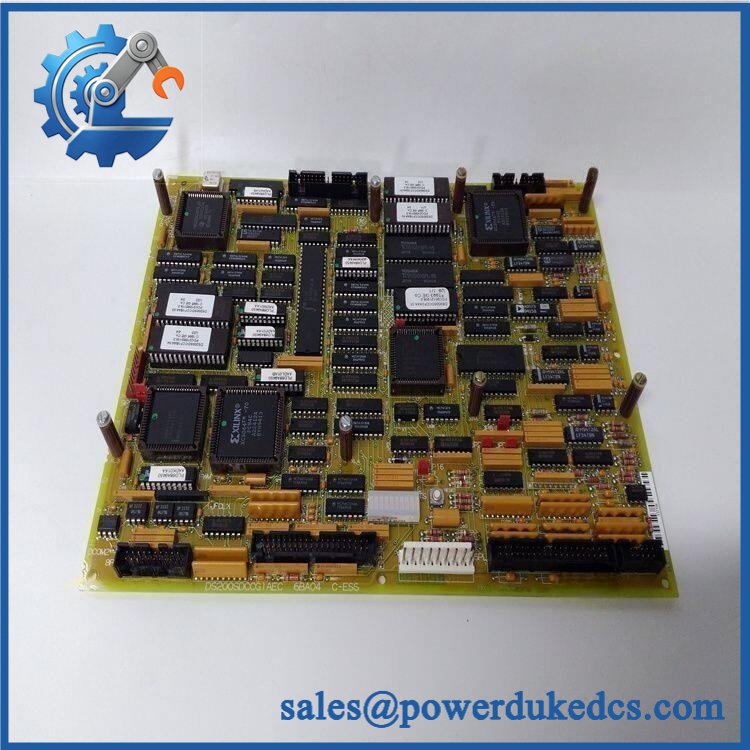
GE DS200SDCCG4AGD
🚨 Global Compliance & Industry Certifications
The DS200SDCCG4AGD is an electronic control board used inside a larger Mark V turbine-control system. Certification should therefore be claimed at the equipment/configuration level unless a revision-specific certificate supports a standalone claim.
- CE Mark: May apply to the complete Mark V equipment configuration. Do not infer a standalone CE declaration from the PCB part number.
- UL/cUL: Certification can depend on the cabinet and system configuration. A universal UL/cUL statement for every revision is not established by the accessible records.
- ATEX/IECEx: Do not assume hazardous-area certification. Installation in a classified area requires the complete certified control and enclosure arrangement.
- Marine approvals: No revision-specific DNV approval was established for this exact SDCC board.
- Electrical safety: The board operates inside a drive system containing hazardous voltages. Technical records specifically warn that internal drive components can present shock and burn hazards when energized.
- Functional safety: Do not assign a SIL level to the SDCC PCB by itself. Any safety claim belongs to the engineered turbine protection/control function and its complete architecture.
- Audit package: Retain the actual PCB photograph, full part number, functional/artwork revision, serial/date code, applicable manual, supplier COO, test record, and any certification documents.
Verify specific lot certifications with OEM.
🚨 Long-Term Storage & Asset Preservation Guide
Keep the SDCC in an ESD shielding bag from receipt through installation. The three-processor architecture, memory devices, connectors, and jumper interfaces make uncontrolled static handling an unnecessary storage risk.
Preserve the memory and configuration identity. Do not remove, swap, or re-seat memory devices simply to inspect the board. Record all installed memory identifiers, firmware markings, jumper settings, and revision labels with the inventory record. The G4A family has different firmware and expanded parameter storage versus G1A boards, so configuration traceability matters.
Control temperature and moisture. Store indoors under stable conditions, preferably below 60% RH, with sealed packaging and suitable desiccant. Inspect connectors, memory sockets, solder joints, and the conformal/normal-coating surface for corrosion or contamination during periodic warehouse audits.
Do not use repeated power cycling as a storage check. For legacy control boards, document the last validated test date, hardware revision, memory configuration, jumper arrangement, and packaging state. A controlled functional test before issue is more useful than casual shelf energization.
Physical Installation Prerequisites
- Power Isolation: De-energize the Mark V drive and all relevant auxiliary/control supplies before removing the board. High-voltage energy can remain in the drive after normal shutdown.
- Board Position: Confirm the exact Mark V board slot and associated drive configuration before removal.
- Power Supply Interface: Verify the two board connectors associated with the Power Supply Interface Board; one carries I/O signals and the other provides DC voltage.
- Memory Identification: Match the installed memory/PROM configuration before commissioning a replacement.
- Jumpers: Photograph and record all hardware jumper settings. Do not rely on memory or handwritten notes made after removal.
- Diagnostic Access: Ensure the cabinet door and installation position allow visual access to the 10 diagnostic LEDs during controlled startup.
- P15 Measurement: Where troubleshooting requires it, use the documented P15 regulated +15 VDC test point with appropriate measurement precautions.
- Cooling: Keep cabinet airflow paths and board clearances unobstructed. Do not bundle ribbon cables tightly against heat-producing components.
- Grounding: Verify cabinet protective-earth continuity before re-energizing.
- ESD: Use a grounded wrist strap and ESD-safe surface when handling the PCB.
- Cable Handling: Label ribbon connectors before removal and inspect every mating contact for bent pins or contamination.
Secondary installation references also warn technicians to document jumper/DIP positions before replacing the SDCC. That is good field practice for this board family because configuration differences can affect turbine operation.
Buyer’s FAQ
Q1. What HS tariff code should be used for GE ?
Do not classify it as a generic “PLC” or “computer board” without reviewing its technical function. The is a dedicated turbine-drive control PCB, so an importer may evaluate headings covering electrical control apparatus or parts thereof.
For commercial documentation, use a precise description such as “GE Mark V Drive Control Card, SDCC turbine-control PCB” and have the importer or customs broker confirm the final national tariff code.
Q2. What Country of Origin should appear on the COO?
Use the origin of the actual physical board being shipped, supported by the nameplate and supplier traceability. Secondary inventory records commonly report USA for this part, but that should be treated as supporting information rather than copied automatically to every historical unit.
For audit purposes, retain the actual-unit photograph, serial/date-code record, supplier COO statement, and commercial invoice.
Q3. Should I insure shipment of ?
For a legacy Mark V controller board, shipment insurance is advisable when replacement exposure is significant. Use ESD shielding, rigid board support, connector protection, and moisture control; never allow the PCB to shift freely inside the carton.
Photograph the front and rear of the board, revision markings, memory area, connectors, and packaging before dispatch.
Q4. Does include the latest firmware pre-loaded?
Do not assume it does. The G4A SDCC family is specifically distinguished from G1A boards by its different firmware and expanded EE parameter storage area. The exact firmware/configuration baseline should therefore be verified against the installed Mark V application before commissioning.
Q5. Can I substitute a G1A SDCC for ?
No—not without engineering approval. The G4A family was developed for TC2000 applications and has different firmware and expanded parameter storage compared with G1A SDCC hardware. A visually similar SDCC board can therefore be electrically present but operationally wrong for the application.











 Start Chat


