

Description
- Model: DS200SDCIG1ABA
- Brand: General Electric (GE)
- Series: Mark V DS200 / DC2000
- Part Type: SDCI DC Power Supply and Instrumentation Board
- Core Function: Supplies logic and signal-level power while providing instrumentation and interface circuitry for compatible GE DC2000 drive equipment.
- Key Specs: Mark V SDCI G1 architecture, three revision fields, five documented fuse positions, three configuration elements, multiple DC supply rails, 115 VAC auxiliary circuitry, and compatibility with DC2000 drives up to 600 VAC. The applicable GE manual is GEI-100173.
Product Introduction
The DS200SDCIG1ABA occupies the power-conditioning and instrumentation layer of compatible GE DC2000 drive equipment. It is identified as an SDCI DC Power Supply and Instrumentation Board, providing logic power and interface circuitry while also handling several motor and line measurement functions. GE-related technical records associate the board with the broader Mark V turbine and drive-control environment and specify use with DC2000 equipment rated up to 600 VAC.
From a maintenance perspective, this board needs more careful identification than the generic description “power supply card” suggests. The G1 board family contains specific fuse circuits, jumper functions, and a selector switch, and the supplied A/B/A suffix identifies the functional and artwork revisions. Do not normalize the part number to DS200SDCIG1 during inventory entry (the missing suffix can conceal the exact hardware revision).
Core Technical Specifications
| Parameter | Value |
|---|---|
| Manufacturer | General Electric (GE) |
| Part Number | DS200SDCIG1ABA |
| Product Family | Mark V DS200 |
| Functional Acronym | SDCI |
| Product Type | DC Power Supply and Instrumentation Board |
| Associated Drive Family | GE DC2000 |
| Maximum Associated Drive Voltage | Up to 600 VAC |
| Functional Revision 1 | A |
| Functional Revision 2 | B |
| Artwork Revision | A |
| PCB Coating | Normal coating |
| Applicable Manual | GEI-100173 |
| FU1 Function | 115 VAC power supply fuse |
| FU2 Function | DC signal-level power-supply fuse |
| FU3 Function | DC signal-level power-supply fuse |
| FU5 Function | Internal NRX / field-MOV assembly fuse |
| FU6 Function | Internal NRX / field-MOV assembly fuse |
| Configuration Elements | JP1, JP2, and SW1 |
| JP1 Function | MD contactor control-source selection |
| JP2 Function | MA AC contactor dropout-time selection |
| SW1 Function | AC-line CT burden selection based on nominal DC output current |
| Published Supply Rails | +5 VDC, ±15 VDC, ±24 VDC, and 115 VAC circuits are reported for the SDCI family |
| Published +5 VDC Rating | 4 A reported for the family |
| Published ±15 VDC Rating | 0.4 A reported for the family |
| Published 115 VAC Rating | 0.4 A reported for the family |
| Field Control | Armature SCR-gating and motor-field circuitry |
| Instrumentation | AC/DC motor and line signal monitoring |
| Processor | None established for the SDCI board |
| User Memory | None established |
| Firmware | No standalone firmware identified |
| Ethernet | None |
| Independent Fieldbus | None |
| Reported Operating Temperature | 0°C to +60°C for the DS200SDCI family; verify exact cabinet specification |
| Reported Shipping Weight | Approximately 2.61 lb / 1.18 kg |
| Dimensions | Exact OEM dimensions not verified; commercial records conflict |
| Lifecycle | Legacy / obsolete |
The exact-board record confirms the A/B/A revision structure, five fuse positions, JP1, JP2, and SW1, and a reported shipping weight of 2.61 lb. It also identifies GEI-100173 as the applicable replacement procedure manual.
Secondary technical documentation reports +5 VDC at 4 A, ±15 VDC at 0.4 A, ±24 VDC rails, and 115 VAC at 0.4 A for the SDCI family. Because these figures are not presented as a complete revision-specific electrical table for DS200SDCIG1ABA in the reviewed material, use the original GE schematic and cabinet documentation for final engineering acceptance.
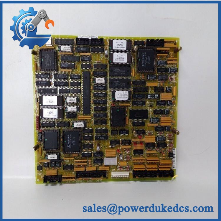
GE DS200SDCIG1ABA
Application Scenarios & Pain Points
Micro-case — the drive remains energized but several instrumentation signals become abnormal. The SDCI board is a common interface point for multiple power and measurement circuits, so a single board-level problem can affect more than one observed parameter. Check the supply fuses, external wiring, and associated drive circuits before condemning the PCB.
Within motor-drive systems, the board provides logic power and instrumentation circuitry, including circuits associated with armature SCR gating, motor-field functions, and AC/DC line measurements. This makes it different from a simple low-voltage power converter.
For legacy Mark V installations, the board can also support motor-control applications associated with turbine auxiliary equipment and other industrial drive loads. GE-related records identify the wider Mark V family in gas, steam, and wind turbine applications.
At cabinet temperatures around 50°C, inspect the fuse area, connectors, power components, and surrounding airflow. A published commercial specification gives 0°C to +60°C for the DS200SDCI family, but the exact temperature requirement should be taken from the installed drive cabinet documentation.
🚨 Common Error Codes & Diagnostic Symptoms
This board is a power and instrumentation PCB rather than a programmable CPU. It therefore has no independent modern numerical fault-code table.
Symptom/Code: A fuse-status LED is illuminated → Diagnosis: The associated SDCI fuse may have opened. Documented fuse functions include FU1, FU2, FU3, FU5, and FU6, each serving a different power or field circuit. → Action: Identify the affected fuse circuit and determine the cause before replacing the fuse or board.
Symptom/Code: Multiple drive instrumentation readings become abnormal → Diagnosis: Possible loss of one of the SDCI supply rails, signal-conditioning fault, CT-burden configuration issue, or external instrumentation wiring problem. → Action: Verify the relevant supply rails and external signals before replacing the SDCI board.
Symptom/Code: MD/MA contactor behavior differs after board replacement → Diagnosis: JP1 and JP2 configuration may not match the original installation. JP1 controls the MD control source, while JP2 selects MA AC-contactor dropout timing. → Action: Compare jumper positions with the original board and approved drive documentation before returning the drive to service.
🚨 Cross-Reference & Lifecycle Migration
Revision and Related-Part Identification
The exact identity is:
DS200SDCIG1ABA
The broader family includes DS200SDCIG1, DS200SDCIG1A, DS200SDCIG1AEB, DS200SDCIG1AFB, and other suffix variants. These are related SDCI assemblies, but the suffix can represent different functional/artwork revisions. Therefore, a shorter family number should not be treated as an automatic replacement.
Current legacy records also list DS200SDCIG2 and its variants as separate SDCI boards. No sufficiently authoritative evidence was found to claim that a G2 assembly is a universal drop-in replacement for the specific G1ABA revision. Treat any G1-to-G2 migration as an engineering-controlled substitution.
Firmware Requirement
No firmware flashing is required for DS200SDCIG1ABA itself.
The SDCI board is a power/instrumentation assembly containing supply circuits, fuses, analog instrumentation, SCR-gating interfaces, and hardware configuration elements. No user-programmable firmware or application memory was established for this board.
Configuration matters, however. JP1, JP2, and SW1 must match the installed drive application.
Lifecycle Status
Status: Obsolete / Legacy
Current legacy records identify as a discontinued Mark V spare, although service inventories continue to carry the part.
For buffer stock, preserve the exact G1ABA suffix and configuration record. Where the SDCI board is critical to a drive, a verified spare with documented fuse and jumper state is preferable to an unverified family-level substitute.
Field Engineer’s Tech Notes
Warning 1 — Never replace a blown fuse without finding the cause.
The SDCI board contains several separately protected circuits, including field and signal-level supplies. GE documentation identifies a dedicated fuse for the 115 VAC circuit and separate protection for DC signal and NRX/field-MOV circuits. A replacement fuse that opens again is a fault indicator, not an invitation to install a larger fuse.
Warning 2 — Photograph JP1, JP2, and SW1 before removal.
These settings are part of the drive’s electrical configuration. In particular, SW1 selects the AC-line CT burden in relation to nominal DC output current, while JP1 and JP2 affect contactor-control behavior. Record the original positions before disconnecting the board (especially on an old cabinet with incomplete drawings).
Strict QA & Testing SOP
Step 1 — Exact identity verification
Confirm and record the three revision fields: A / B / A. Photograph all labels and secondary identification marks.
Step 2 — Mechanical inspection
Inspect the PCB, terminal points, connectors, fuse holders, mounting hardware, and protective coating for corrosion, cracking, contamination, and previous repair work.
Step 3 — Fuse inspection
Check FU1, FU2, FU3, FU5, and FU6 for correct type, visible damage, heat discoloration, and secure mounting. Confirm the fuse specification from GEI-100173 before replacement.
Step 4 — Configuration capture
Photograph JP1, JP2, and SW1 and record their exact settings. Do not adjust these components during routine inspection.
Step 5 — PCB electrical pre-check
With the board completely isolated, perform controlled continuity and resistance checks at documented test points. Do not use a guessed external supply voltage.
Step 6 — Low-voltage rail test
On an approved test fixture, verify the applicable DC supply rails, including the published +5 V and ±15 V circuits. Compare measured values with the original GE documentation.
Step 7 — AC auxiliary-circuit test
Verify the applicable 115 VAC circuit using the correct controlled test source and protection arrangement.
Step 8 — Instrumentation test
Apply controlled simulated signals to the relevant instrumentation inputs and verify expected measurement response.
Step 9 — Contactor-control verification
Confirm that JP1/JP2-dependent functions behave correctly on an approved test setup. Verify that the board does not produce unintended contactor commands.
Step 10 — Field/drive interface test
Where an approved test environment is available, verify the applicable armature, field-control, and line-instrumentation interfaces.
Step 11 — Thermal observation
Operate the board under representative load and monitor the power-supply and fuse areas for abnormal heating.
Step 12 — Extended run test
Observe the board through repeated operating cycles and monitor for intermittent supply loss, fuse operation, unstable instrumentation, or abnormal electrical behavior.
Step 13 — Documentation
Record test measurements, fuse condition, jumper settings, revision information, photographs, and QA disposition.
Step 14 — ESD-safe packaging
After testing, place the board in ESD shielding material. Protect the fuse holders, connectors, terminal hardware, and board edges against mechanical impact.
Test videos are available for applicable units tested on a compatible GE /Mark V test setup.
Buyer’s FAQ
Can I hot-swap the ?
No general hot-swap procedure should be assumed. This board can interface with 115 VAC and drive-related high-energy circuits, and GE’s replacement procedure requires qualified personnel and complete power isolation. Remove the relevant drive power sources, allow stored energy to dissipate, and verify zero energy before handling the board.
How do I verify a New Original ?
Request photographs of the actual board, including the complete part number, A/B/A revision, fuse positions, JP1/JP2/SW1 settings, connectors, and PCB condition. The physical revision is important because the DS200SDCI family contains multiple suffix variants.
What HS tariff code should be used?
The final HS/HTS classification depends on the importing country’s tariff schedule and the verified customs function of the product. Because this is a DC power supply and instrumentation board for industrial drive equipment, the broker should classify it according to its actual principal function rather than a generic PLC-module description.
Use a clear commercial description such as GE Mark V SDCI DC power supply and instrumentation board for drive equipment, then obtain the destination-country tariff classification from the customs broker.
Does the board include the latest firmware?
No. is not identified as a firmware-managed CPU or intelligent communications module. Its functions are implemented through power circuits, instrumentation circuitry, fuses, jumpers, and the selector switch.
For replacement control, the relevant information is the hardware revision and JP1/JP2/SW1 configuration, not a firmware package.
What is the Country of Origin?
Commercial records for this part have identified the United States as the origin, but supplier database information should not be treated as definitive customs evidence.
For a formal customs declaration, use manufacturer or supplier-supported origin documentation and keep the COO consistent across the commercial invoice, packing list, and Certificate of Origin when required.
Should shipping insurance be used?
For a legacy Mark V/ board, assess insurance against replacement value and plant criticality rather than weight alone. Photograph the actual PCB, fuse section, revision marking, connectors, and packaging before carrier handoff, then retain those records with the shipment documents.
What warranty should I expect?
Warranty depends on the supplier’s written commercial terms and the condition category of the board. For this obsolete GE assembly, obtain the warranty period, functional-test scope, actual-board photographs, revision information, and return conditions before purchase. A third-party warranty should not be represented as a GE factory warranty unless separately documented.











 Start Chat


