

Description
- Brand: GE General Electric
- Full Model Number: DS200SDCIG2AHB
- Lifecycle Status: Obsolete / legacy Mark V DS200
- Core Function: DC power supply and instrumentation interface board for GE DC2000 drive applications
- Technical Specs: +5 VDC at 4 A; ±15 VDC at 0.4 A; ±24 VDC supply circuits
- Additional Supply: 115 VAC at 0.4 A
- Drive Application: GE DC2000 / Mark V
- Input Capability: Applications supporting drive input voltages up to 600 VAC
- Diagnostics: Onboard fuse circuits with LED fault indication
- Board Revision: G2AHB
- Condition: New Surplus / Reconditioned subject to physical inventory confirmation
- Stock Status: Availability to be confirmed before PO
- Shipping: Emergency dispatch cutoff to be confirmed with sales
The DS200SDCIG2AHB is identified as a GE Mark V SDCI DC Power Supply and Instrumentation Board. Available references associate it with GEI-100173 and the DC2000 drive family.
Obsolescence & Supply Chain Deep Dive
Replacing a failed board in a legacy GE Mark V installation can become a sourcing problem long before the engineering problem is solved. The DS200SDCIG2AHB is part of the discontinued DS200 product family, so normal factory replenishment is not the same option available for current-generation control hardware. The board provides power-supply and instrumentation functions for DC2000 drive applications, including +5 VDC, ±15 VDC, ±24 VDC and 115 VAC supply circuits. When an installed board fails, obtaining the correct revision from surplus inventory can reduce the exposure created by extended repair cycles or a forced control-system replacement.
From a TCO perspective, replacing one failed board is materially different from replacing an entire legacy drive or control architecture. The DS200SDCIG2AHB can preserve the existing hardware arrangement when the installed drive, wiring, connectors, jumpers and associated control configuration remain suitable. Its documented hardware includes configurable elements such as JP1, JP2 and SW1, so the replacement should be matched against the removed board before energization. A board-level replacement also avoids the engineering, commissioning, panel modification and software-integration costs associated with a larger migration. For obsolete equipment, however, procurement should treat remaining compatible inventory as a lifecycle risk rather than assume indefinite availability.
Compatibility & Replacement Matrix
| Replacement Item | Assessment | Procurement / Engineering Action |
|---|---|---|
| DS200SDCIG2AHB replacing the same DS200SDCIG2AHB revision | Drop-in Replacement | Verify part number, revision, connector condition and jumper/switch settings before installation |
| replacing another DS200SDCIG2A-family revision | Hardware Compatibility Requires Verification | Do not approve solely from the base DS200SDCIG2A designation; compare revision-specific documentation and installed configuration |
| Firmware conversion | Normally Not Required for the Board Itself | This is a power supply/instrumentation board rather than a standalone programmable CPU; verify the complete drive configuration separately |
| Full drive/control migration | Not Required for Like-for-Like Board Replacement | Consider only when compatible replacement inventory can no longer support the installed system |
| Estimated field replacement labor | Approximately 2–4 hours | Site shutdown, isolation, board removal, wiring verification and functional checks can extend the window |
| Estimated larger-system migration | Project-dependent | Requires engineering review, panel work, configuration, testing and commissioning |
The is described as a revised DS200SDCIG2 board, and available technical references identify three configurable hardware elements: JP1, JP2 and SW1.
Field Traps to Watch Out For
Revision mismatch: The DS200SDCIG2 family contains multiple suffix revisions, including DS200SDCIG2ABA, DS200SDCIG2ABB, DS200SDCIG2AEB, DS200SDCIG2AFB, DS200SDCIG2AGB and . Do not approve a substitute simply because the base number matches.
Jumper and switch configuration: JP1 controls the MD control source, JP2 relates to MA AC contactor drop-out timing, and SW1 selects CT line burden according to nominal DC output current. The replacement board should be compared with the removed board and the applicable GE documentation before startup.
Static damage: The board is sensitive to electrostatic discharge. Keep it in static-protective packaging until installation and use appropriate ESD handling procedures during replacement.
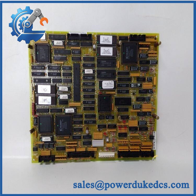
GE DS200SDCIG2AHB
Quality Assurance & Testing SOP
For surplus inventory, the inspection objective is to establish traceability, physical integrity and electrical readiness before shipment. Each should pass a documented receiving and pre-shipment inspection rather than being released solely on model-number matching.
- Part-number verification: Confirm against the board label, identification markings and purchasing record.
- Revision verification: Record the complete board revision and compare it with the requested replacement specification.
- OEM anti-counterfeit visual inspection: Examine PCB markings, labels, connectors, solder workmanship, component condition and revision identifiers for inconsistencies.
- PCB condition inspection: Check for corrosion, contamination, cracked components, damaged traces, bent connector pins and evidence of overheating.
- Fuse inspection: Verify FU1–FU3, FU5 and FU6 condition and inspect their associated LED indicators. The documented board design uses onboard fuse/LED diagnostic circuits.
- Jumper configuration check: Record JP1 and JP2 positions and compare them with the customer’s removed board or approved configuration.
- SW1 configuration check: Confirm the CT burden selection before shipment.
- Power-on self-test: Where the available test fixture supports the board, energize the unit under controlled conditions and check supply outputs and diagnostic indicators.
- DC output verification: Measure applicable +5 VDC, ±15 VDC and ±24 VDC supply circuits against the approved test limits.
- 115 VAC circuit verification: Verify the applicable 115 VAC supply circuit under controlled test conditions.
- I/O and instrumentation verification: Check accessible instrumentation and interface circuits using the appropriate test fixture.
- Thermal observation: Monitor the board during the defined test period for abnormal heating, unstable output or unexpected electrical behavior.
- Final visual inspection: Recheck connectors, mounting points, labels and PCB condition after testing.
- Packaging control: Place the tested board in ESD-protective packaging with sufficient mechanical protection for international transport.
- QC record: Record model number, revision, serial/identification markings where available, inspection result and test date.
Actual test limits must follow the applicable GE documentation and the customer’s equipment configuration; generic bench measurements should not be treated as a substitute for the installation-specific acceptance procedure.
Procurement & Lifecycle FAQ
Is the genuinely in stock, and what is the emergency-shipping cutoff?
Availability should be confirmed against the physical inventory before the purchase order is released. Current external listings show this model as available from some industrial suppliers, but those listings do not establish another supplier’s inventory position. For emergency requirements, request same-day availability, warehouse release time and carrier cutoff together rather than relying on a generic lead-time statement.
How do you verify the condition and authenticity of an obsolete ?
The procurement record should include the complete model number, revision, physical inspection result and available identification markings. New-surplus units should be distinguished from previously installed or refurbished boards. Visual inspection should cover PCB markings, connectors, components, solder condition and signs of previous field use. ESD-safe handling and protective packaging should also be documented before shipment.
Are there firmware compatibility issues before issuing the PO?
The is a DC power supply and instrumentation board rather than a standalone programmable controller requiring a conventional firmware flash. The more important compatibility checks are the exact board revision, drive application, jumper positions, SW1 configuration, connectors and associated DC2000 system configuration. Engineering approval should therefore verify the complete installed configuration rather than treating the base DS200SDCIG2A number as sufficient.
What warranty terms and return conditions should procurement request?
Warranty duration and return conditions depend on the supplier and the specific stock condition. The quotation should state the warranty period, start date, DOA procedure, return authorization process and whether the warranty covers replacement, repair or refund. For obsolete control boards, request these terms in writing before the PO is released.
Is buying a replacement board preferable to upgrading the complete Mark V system?
That depends on the plant’s remaining lifecycle requirement, installed-base condition, criticality and migration budget. For a single failed board in an otherwise serviceable installation, a verified replacement can avoid the engineering and commissioning costs associated with a complete migration. If multiple boards are approaching failure or compatible inventory is becoming difficult to secure, procurement should evaluate a planned modernization program instead of treating each failure as an isolated purchase.











 Start Chat


