

Description
- Brand: GE
- Full Model Number: DS200SLCCG1AFG
- Lifecycle Status: Obsolete / Legacy
- Core Function: Mark V LAN Communications Card
- Network Functions: DLAN + ARCNET
- Processor: LCP LAN Control Processor
- Memory: 2 × removable EPROM devices; dual-ported RAM
- Display: 16-position alphanumeric display
- Connectors: 2PL, 3PL, 10PL, ARCPL, KPPL
- Configuration: Hardware jumpers and WJ wire jumpers
- Mounting: Four standoffs on compatible SDCC assembly
- Manual: GEI-100162
- Revision History: 3 significant revisions; first two reported as backward-compatible
- Stock & Condition: Specialist surplus / tested replacement stock; exact lot condition to be confirmed
- Emergency Shipping: Dispatch subject to physical-stock verification and carrier cutoff
The DS200SLCCG1AFG is identified as a Group 1 GE Mark V SLCC LAN Communications Card. Its documented architecture includes both DLAN and ARCNET circuitry, an onboard LCP, removable EPROM storage, dual-ported RAM, and a programmer-keypad interface.
Obsolescence & Supply Chain Deep Dive
When a Mark V communication card fails, the problem is rarely limited to the PCB purchase. A communication outage can prevent normal interaction between the control processor and connected drive or exciter equipment, turning a relatively small board failure into an extended maintenance window. The DS200SLCCG1AFG is already part of a legacy product family, and current specialist listings identify it as obsolete while reporting available replacement inventory. The board supports both DLAN and ARCNET, connects to the surrounding control architecture through 2PL, 3PL, 10PL, ARCPL, and KPPL, and includes an LCP-based communication subsystem.
From a TCO perspective, preserving the existing Mark V installation can be financially preferable to a full control-system migration when the surrounding hardware remains serviceable. The immediate value comes from restoring an installed communication path without redesigning the host cabinet, application logic, field wiring, or associated control hardware. The key caveat is memory configuration: DS200 SLCC boards are commonly supplied with the U6 and U7 EPROM sockets empty, while a DS215-level replacement can include the programmed EPROM devices. That distinction can materially change replacement labor and commissioning time. —For emergency projects, verify whether the supplied board already contains the required EPROMs before the PO is finalized.
Compatibility & Replacement Matrix
| Replacement Item | Engineering Assessment |
|---|---|
| Replacement Classification | Conditional Drop-in Replacement |
| Physical Architecture | Designed for compatible GE Mark V DS200 installations |
| Host Platform | GE Mark V drive and exciter control systems |
| Network Function | DLAN and ARCNET |
| Software / Firmware Action | Normally no conventional field firmware flash on the PCB itself; application memory must be verified |
| EPROM Requirement | Critical check; U6/U7 program-storage devices may be absent on DS200-level boards |
| Hardware Modification | Normally no PCB modification; jumper settings must match the installed application |
| Mounting | Four standoffs on the compatible SDCC assembly |
| Keypad Interface | KPPL connector supports the programmer/keypad assembly |
| Typical Board-Swap Labor | Approximately 2–4 labor hours, excluding troubleshooting and site-specific commissioning |
| Budgetary Field Labor | Approximately USD 300–1,000 depending on site labor rates and outage procedures |
| Commissioning Scope | Power-up diagnostics, communication verification, keypad/display check, and application-level functional test |
Field Traps
EPROM mismatch:
This is the most important purchasing hazard. Current technical documentation reports that DS200 SLCC boards may ship with U6 and U7 EPROM sockets empty. If the engineer expects the replacement to arrive already populated with the operating program, confirm the actual memory configuration before shipment. A DS215-level option may be more appropriate where programmed EPROM transfer is not practical.
Revision mismatch:
The DS200SLCCG1AFG is reported with three significant revisions, with the first two described as backward-compatible. Do not treat that statement as universal interchangeability across every SLCC configuration. Compare the full part number, revision markings, EPROM arrangement, jumper configuration, and host-system application before approving substitution.
Jumper configuration:
The board contains manually adjustable hardware jumpers and WJ wire jumpers. Specific selections can affect DLAN driver configuration and DLAN isolation; J19 is also used in the processor crystal connection. Record the original positions before removal.
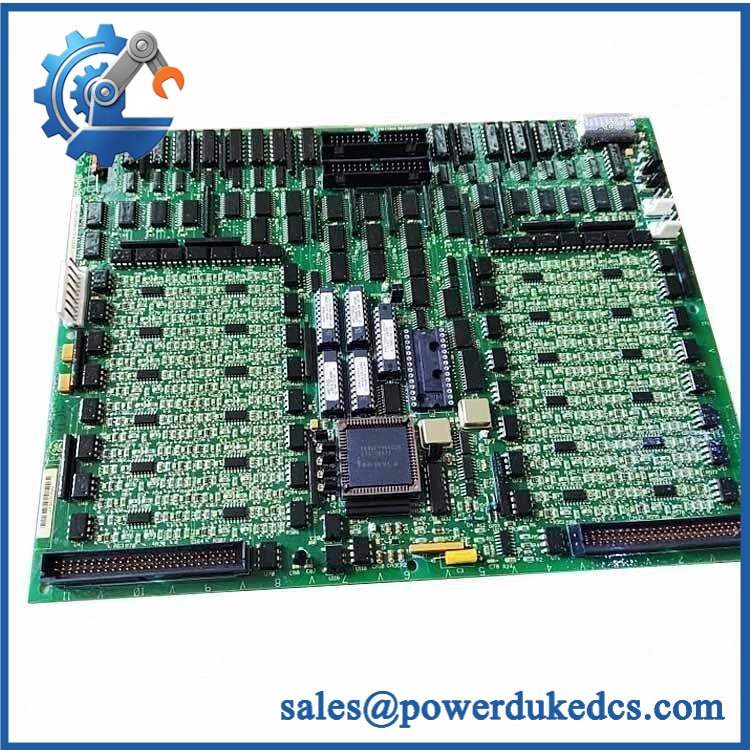
GE DS200SLCCG1AFG
Quality Assurance & Testing SOP
A surplus DS200SLCCG1AFG should not be released solely on the basis of a clean PCB appearance. The acceptance process should establish identity, revision, memory condition, connector integrity, and operational behavior.
OEM anti-counterfeit visual inspection
Verify the GE board identification, complete DS200SLCCG1AFG marking, revision characters, PCB construction, connector geometry, component population, silkscreen consistency, solder quality, and physical finish. Photograph both sides of the board and the identification area.
Memory verification
Inspect the U6 and U7 positions specifically. Record whether the EPROM devices are installed, absent, or supplied separately. This information should appear on the QC record because it directly affects field replacement planning.
Power-on self-test and diagnostic check
Install the board in an appropriate Mark V test environment and verify startup behavior. Where the host rack exposes RUN/ERR indicators, record the startup state and confirm that no unexpected system fault remains. The SLCC itself also provides a 16-position alphanumeric display used with its display controller and programmer interface; verify expected display operation during the test.
Communication-path testing
Exercise the relevant DLAN and ARCNET communication paths through a controlled test setup. Confirm that the LCP initializes correctly and that the board exchanges data with the associated controller hardware.
I/O and interface load testing
Perform representative interface testing through 2PL, 3PL, 10PL, ARCPL, and KPPL as applicable to the test fixture. Check connector continuity, signal stability, intermittent faults, and keypad/display interaction. Do not substitute a basic continuity check for an actual communication test.
Jumper and configuration audit
Record all JP and WJ positions before shipment. Compare the configuration against the customer’s original board or approved application documentation. Never reset jumpers to a generic position simply because the replacement board is from the same product family.
ESD and mechanical inspection
Handle the board within an ESD-controlled environment. Inspect connector pins, board edges, standoffs, display area, and solder joints for transport or storage damage.
Final release package
The QC package should include part-number verification, revision photographs, memory-population status, test results, visual inspection records, and packing photographs. Test videos can also be retained for the customer file when required.
Procurement & Lifecycle FAQ
Is the currently available for emergency shipment?
Specialist technical listings currently show , with same-day shipment advertised by at least one supplier. Because this is obsolete Mark V hardware, that status should be treated as supplier-specific and lot-specific. For emergency procurement, obtain physical-stock confirmation and the day’s carrier cutoff before releasing the PO.
How can authenticity and condition be verified for an obsolete surplus board?
Require the exact identification, revision markings, PCB photographs, connector inspection, and documented memory status. For critical applications, request functional test evidence and a written condition statement such as New Surplus or Tested Replacement. Do not accept “equivalent” wording without a documented compatibility review.
Does the require a firmware flash?
The primary concern is not a routine firmware-flashing procedure. The more important issue is whether the board contains the required U6/U7 EPROM program devices and whether its jumper configuration matches the installed application. GE documentation and current technical references identify removable EPROM-based program storage on the SLCC architecture.
Is a direct replacement for every SLCC card?
No. It should be treated as a conditional replacement. The G1 group, complete suffix, revision level, memory configuration, jumper positions, DLAN/ARCNET requirements, and host Mark V application must all be checked. The first two reported revisions are described as backward-compatible, but that does not remove the need for application-level verification.
What warranty and return terms should be specified in the PO?
For obsolete electronics, define the exact part number and revision, physical condition, test status, warranty duration, DOA criteria, return authorization procedure, and freight responsibility for approved warranty claims. Warranty periods vary by supplier and condition, so the commercial quotation should control rather than relying on a generic catalog statement.











 Start Chat


