

Description
- Series: Mark V Speedtronic
- Part Type: TCEB Protective Termination Expander Board
- Functional Revision: B
- Secondary Revision: A
- Artwork Revision: A
- Approx. Physical Dimensions: 7.0 × 6.25 in (177.8 × 158.8 mm); verify the installed cabinet drawing before mechanical work
- Estimated Net Weight: Approx. 0.7 kg
- Estimated Shipping Weight: Approx. 1.0–1.3 kg packed, depending on ESD and impact protection
- Connectors: 3 bayonet connectors; 1 × 26-pin connector; 4 × 10-pin connectors; 3 × 20-pin connectors
- Signal Transformers: 4
- Board Supply: Host Mark V backplane supply, with +5 VDC identified in current technical records
- What’s in the Box: DS200TCEBG1BAA board, ESD shielding, connector protection, cushioning; manuals and auxiliary hardware only when specifically included
- Installation: Mark V turbine-control cabinet / VME rack
- Handling: ESD-controlled storage and installation required
Current technical records identify DS200TCEBG1BAA as the TCEB Protective Termination Expander Board, with four signal transformers and the listed multi-pin/bayonet connector arrangement.
Product Introduction
The TCEB sits in the Mark V signal architecture where several protection and turbine-control circuits converge. DS200TCEBG1BAA is used as a Protective Termination Expander Board / Common Circuits EOS Board, handling signal routing and conditioning between termination circuitry and other Mark V boards. Technical references associate its connections with PT/CT signals, magnetic-pickup and flame-detection signals, and conditioned signals routed toward the TCEA/TCCB portions of the control system.
This board deserves strict revision control. The complete G1BAA code identifies functional revision B, secondary revision A, and artwork revision A; similar TCEB boards should not be treated as automatically interchangeable. Four signal transformers and three 20-pin ribbon interfaces also create a substantial reconnection risk during maintenance (one incorrectly routed harness can affect several related signals at once).
Core Technical Specifications
| Parameter | Value |
|---|---|
| Manufacturer | GE General Electric |
| Part Number | DS200TCEBG1BAA |
| Product Series | Mark V Speedtronic |
| Functional Acronym | TCEB |
| Product Type | Protective Termination Expander / Common Circuits EOS Board |
| Functional Revision 1 | B |
| Functional Revision 2 | A |
| Artwork Revision | A |
| PCB Coating | Normal coating |
| Signal Transformers | 4 |
| Bayonet Connectors | 3 |
| 26-Pin Connector | 1 |
| 10-Pin Connectors | 4 |
| 20-Pin Connectors | 3 |
| Typical 20-Pin Labels | JKX, JKY, JKZ |
| Typical Signal Groups | PT/CT, magnetic pickup, flame detection, conditioned turbine signals |
| Host Power | Mark V backplane; +5 VDC identified in secondary records |
| Approx. Board Size | 7.0 × 6.25 in |
| Estimated Net Weight | Approx. 0.7 kg |
| Memory | No dedicated user-program memory identified for this termination/expander board |
| Firmware | No standalone firmware package established |
| Installation | Mark V VME rack architecture |
AX Control identifies the board as TCEB and documents the three bayonet connectors, four signal transformers, one 26-pin connector, four 10-pin connectors, and three 20-pin connectors. The same source explains the role of the JKX/JKY/JKZ ribbon connections.
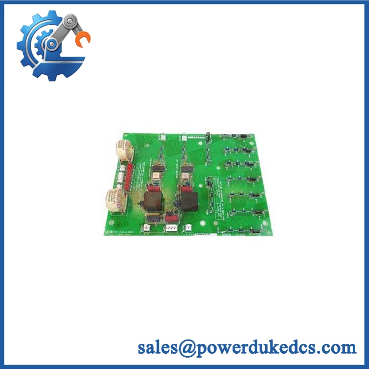
GE DS200TCEBG1BAA
🚨 Global Compliance & Industry Certifications
For DS200TCEBG1BAA, compliance documentation should be associated with the complete Mark V installation and exact board revision. The PCB itself should not be given certification claims that belong to a larger control-system assembly.
- CE Mark: Do not claim standalone CE certification without GE documentation specifically covering DS200TCEBG1BAA.
- UL/cUL: No reliable evidence establishes an independent UL/cUL listing for this exact board.
- ATEX / IECEx: No independent hazardous-area certification was established for .
- Marine Approvals: No DNV, ABS, or LR approval was established for the individual board from the records reviewed.
- EMC: EMC performance should be evaluated at the Mark V system/cabinet level, particularly because this board interfaces with several ribbon-cable signal groups.
- Traceability: Record the complete identity and the B/A/A revision sequence in the asset file.
Why this matters: The TCEB interfaces with protection-related turbine signals, including PT/CT and flame-detection circuits. A wrong board revision or undocumented modification can create an engineering and compliance problem even when continuity checks pass.
Verify specific lot certifications with OEM.
🚨 Long-Term Storage & Asset Preservation Guide
Keep in a metallized ESD shielding bag. The board exposes multiple connector assemblies and signal transformers, so connector contamination and electrostatic handling damage are realistic warehouse risks. Protect the 20-pin connectors from impact; they are not designed to carry package loads.
Keep relative humidity below 60% where practical. Avoid condensation and large temperature swings. The board’s long-term risk is often contact oxidation rather than an obvious PCB defect, particularly after years in uncontrolled warehouse conditions.
Preserve the ribbon-cable map with the spare. Photograph JKX, JKY, and JKZ and all associated connector positions before storage. The board’s three 20-pin interfaces carry different signal groups, and a mislabeled cable can delay restoration significantly. Current technical documentation specifically advises identifying ribbon cables before disconnecting them. (AX Control)
After cold transportation, allow the sealed package to stabilize at room temperature before opening. Inspect connector pins, transformer bodies, solder joints, jumper/header areas, and the PCB surface before energization.
Physical Installation Prerequisites
- Host System: Install only in the approved GE Mark V Speedtronic cabinet/VME architecture.
- Power Isolation: Use the site’s approved shutdown and lockout/tagout procedure before board removal.
- Rack Position: Verify the exact VME slot and cabinet location against the Mark V hardware drawing.
- Ribbon Cables: Label every cable before removal, especially the JKX/JKY/JKZ 20-pin connections. Current technical guidance specifically warns against disturbing their intended routing.
- Connector Inspection: Check all 20-pin, 10-pin, 26-pin, and bayonet connectors for bent contacts, contamination, or mechanical damage.
- Grounding: Preserve the cabinet grounding and signal-reference architecture specified for the installed Mark V system.
- Clearance: Maintain enough access for the dense connector field and ribbon-cable bends. Do not force cables against the board or adjacent cards.
- Cooling: Preserve the VME rack’s designed airflow path; avoid cable bundles directly across cooling openings.
- ESD: Use a grounded wrist strap and ESD-safe work surface.
- Configuration Record: Photograph the complete board before removal, including revision marking and all accessible connection points.
- Final Inspection: Verify every cable against the wiring list before re-energization.
Buyer’s FAQ
Q1. What HS Tariff Code should be used for ?
Do not assign a definitive HS code solely from “protective termination board.” This is a dedicated industrial control-system PCB, and classification can vary by jurisdiction and by how customs treats parts for electrical control equipment. Have the broker confirm the final code using the technical function, commercial invoice description, and destination-country tariff schedule.
Q2. What Country of Origin documentation should accompany the shipment?
Use the actual manufacturing origin supported by supplier or manufacturer records. The export warehouse location is not proof of COO. For audit retention, keep the commercial invoice, packing list, COO statement or certificate where applicable, exact part-number photographs, revision data, and serial/lot information.
Do not assume live removal is acceptable. The board is connected through numerous ribbon and multi-pin interfaces and participates in turbine-control signal processing. Unless the exact Mark V service procedure explicitly authorizes live replacement, treat it as a controlled power-off maintenance operation.
Q4. Does a New Original include the latest firmware pre-loaded?
No standalone firmware should be expected. This is a termination/expander board rather than a programmable CPU, and no dedicated firmware package was established for the exact part. The critical procurement fields are G1BAA revision, connector configuration, signal routing, and physical condition.
Q5. What shipping protection and warranty terms should be required?
Specify the exact revision, physical condition, serial/lot identification where available, warranty period, and return procedure. For international freight, use ESD shielding, rigid cushioning, connector protection, and moisture control; the quotation should also define whether testing includes continuity, connector inspection, and verification of the board’s signal-interface condition.











 Start Chat


