

Description
- Brand: GE General Electric
- Full Model Number: DS200TCRAG1ACC
- Lifecycle Status: Obsolete / Legacy Mark V
- Core Function: Relay output control for compatible Mark V turbine and drive systems
- Top 3 Technical Specs: 30 plug-in relays; 0.5 A relay contact rating; 4 × 34-pin + 4 × 12-pin connectors
- Board Group: Mark V Group 1
- Functional Acronym: TCRA
- Revision: A functional revision + C functional revision + C artwork revision
- PCB Coating: Normal coating
- Assembly: Normal DS200 assembly
- Stock & Condition: New surplus / tested replacement stock; verify actual lot condition before PO
- Shipping: Emergency dispatch subject to physical-stock confirmation and carrier cutoff
The DS200TCRAG1ACC is identified as a GE Mark V TCRA Relay Output Board. Current technical references list three significant revisions, with the first two reported as backward-compatible. The board contains 30 plug-in relays, each listed with a 0.5 A contact rating, plus eight multi-pin connectors.
Obsolescence & Supply Chain Deep Dive
When a legacy Mark V output board fails, the immediate procurement problem is not simply finding a PCB with the same base number. The DS200TCRAG1ACC is an obsolete platform component, while the installed turbine or drive may still depend on its relay-output path for control and indication functions. The board uses 30 plug-in relays and connects through four 34-pin connectors identified as JOR, JOS, JOT, and JO, together with four 12-pin connectors identified as JS3, JS4, JS5, and JS6. That density makes an incorrect substitute, damaged connector, or wiring mistake capable of extending an otherwise localized repair.
The TCO calculation is often driven by outage exposure rather than board price. For an operating Mark V installation, obtaining an exact-revision replacement can avoid the engineering hours associated with a broader control-system redesign, cabinet changes, software redevelopment, and commissioning. A validated surplus board can also shorten the sourcing cycle when original production stock is no longer part of normal supply — although factory-new legacy inventory may carry materially different lead times from immediately available surplus stock. Before the PO is released, record the exact DS200TCRAG1ACC suffix, board revision, relay configuration, connector population, and installed application. The purchase should match the field hardware, not just the product-family name.
Compatibility & Replacement Matrix
| Procurement / Engineering Item | Assessment |
|---|---|
| Replacement Classification | Conditional Drop-in Replacement |
| Host Platform | GE Mark V turbine / compatible drive control systems |
| Core Hardware Function | Relay output switching |
| Relay Count | 30 plug-in relays |
| Relay Contact Rating | 0.5 A per relay as listed by current technical references |
| Firmware Flash Required | No normal standalone firmware-flashing procedure identified for the relay board |
| Software Compatibility | Dependent on the installed Mark V application and associated control boards |
| Hardware Modification | Normally none when replacing an exact matching board; verify configuration before installation |
| Connector Interface | 4 × 34-pin and 4 × 12-pin connectors |
| Typical Board-Swap Labor | Approximately 2–4 labor hours for isolation, documentation, replacement, and functional verification |
| Budgetary Field Labor | Approximately USD 300–1,000, excluding outage costs and specialized commissioning |
| Commissioning | Relay-output verification, connector checks, system diagnostics, and application-level testing |
Field Traps
Revision mismatch:
The DS200TCRAG1ACC is reported with three significant revisions. Although the first two are described as backward-compatible, that should not be interpreted as universal interchangeability across every TCRA configuration. Verify the complete suffix and revision markings before shipment.
Relay and connector identification:
Thirty plug-in relays create a large number of potential output paths. Photograph the original board before removal, label the cable assemblies, and record the JOR/JOS/JOT/JO and JS3/JS4/JS5/JS6 connections. Do not rely on memory during a time-critical outage.
Contact-rating assumption:
The listed 0.5 A figure is a relay contact rating, not a blanket statement that every field load can be switched directly through every installation. Confirm the actual field circuit voltage, load type, inrush characteristics, and terminal-board architecture from the applicable system documentation.
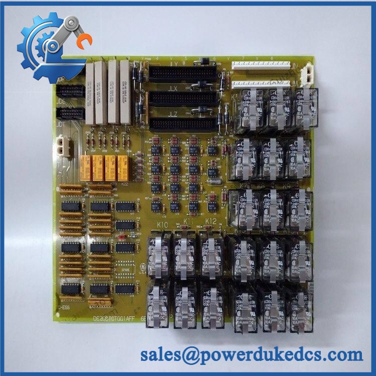
GE DS200TCRAG1ACC
Quality Assurance & Testing SOP
A surplus DS200TCRAG1ACC should be released only after identity, physical condition, relay integrity, connector condition, and available functional behavior have been documented.
OEM anti-counterfeit visual inspection
Verify the complete GE part number, TCRA designation, board revision markings, PCB construction, silkscreen, connector geometry, relay population, component placement, and manufacturing consistency. Capture clear photographs of the identification area and both sides of the PCB.
Relay population inspection
Count all 30 plug-in relays and inspect relay bodies, sockets, pins, and solder joints. Look for cracked housings, corrosion, heat discoloration, loose sockets, and evidence of previous arcing or overheating.
Power-on self-test and system diagnostic check
Install the board only in an appropriate controlled Mark V test environment. Apply the specified board power through the approved test setup and observe host-system diagnostic indications during startup. Record abnormal indications before proceeding to load testing.
Relay-output functional testing
Exercise representative relay channels with a controlled test fixture. Confirm pickup/dropout behavior, contact continuity, output stability, and repeatability. Where the application requires it, test multiple channels rather than accepting a single-channel demonstration as proof of overall board condition.
I/O load testing
Use representative resistive or approved simulated loads within the test fixture’s ratings. Verify that the relay contacts switch correctly without excessive contact resistance, intermittent behavior, or abnormal heating. For field-critical applications, the test procedure should reflect the actual connected load characteristics.
Connector inspection
Check JOR, JOS, JOT, JO, JS3, JS4, JS5, and JS6 for bent pins, contamination, looseness, cracked housings, and mechanical damage. Verify cable retention and connector seating during functional testing.
Thermal observation
After controlled operation, inspect the relay bank and connector areas for abnormal temperature rise, discoloration, or odor. Any unusual heating should trigger additional investigation before release.
ESD and shipment control
Handle the board in an ESD-controlled area. Use an antistatic bag, cushioning around the relay bank and connectors, and moisture protection appropriate for international transportation.
Final QC package
Maintain part-number verification, revision photographs, relay inspection results, functional test records, packing photographs, and test-video evidence where available.
Procurement & Lifecycle FAQ
Is the GE genuinely available for emergency shipment?
Current specialist listings show , with some suppliers advertising same-day or rapid shipment. Because the board is obsolete Mark V hardware, physical-stock confirmation should be obtained immediately before an emergency PO is issued. Confirm whether the offered unit is new surplus, used, refurbished, or functionally tested.
How do you verify the condition and authenticity of an obsolete surplus board?
The purchasing record should include the complete number, visible revision markings, PCB photographs, connector inspection, relay population check, and documented functional-test status. For critical turbine applications, request evidence covering relay operation rather than accepting a visual inspection alone.
Are there firmware compatibility issues?
No normal standalone firmware-flashing requirement has been identified for the TCRA relay output board. The more important compatibility checks are the exact board suffix, revision, Mark V application, connector arrangement, relay configuration, and associated terminal/control hardware. Do not substitute a TCRA family member based only on similar physical appearance.
Is a direct replacement for every TCRA board?
No. It is best treated as a conditional drop-in replacement. The complete suffix and revision must match the installed application, and the external wiring should be verified before energization. Current technical references identify this specific unit as a Group 1 TCRA Relay Output Board with three significant revisions.
What warranty and return conditions should be included in the PO?
Specify the exact part number and revision, supplied condition, functional-test status, warranty duration, DOA definition, return authorization process, and freight responsibility for approved warranty claims. For obsolete electronics, commercial terms can differ substantially by condition, so the quotation should define these points explicitly rather than relying on a generic catalog statement.











 Start Chat


