

Description
- Brand: GE General Electric
- Full Model Number: DS2020PDMAG6
- Lifecycle Status: Obsolete / Legacy
- Core Function: Power distribution for GE Mark VI turbine control systems
- Top 3 Technical Specs: 125 VDC distribution | 115/230 VAC input | Fused feeder and diagnostic circuits
- Stock & Condition: New Surplus / Physical stock confirmation before PO
- Functional Acronym: PDMA
- System Series: GE Mark VI Speedtronic
- Main Distribution: VME racks and I/O termination boards
- Diagnostic Interface: PDM diagnostic signals routed through the control-system interface
- Reference Documentation: GEH-6421 Mark VI System Guide
Obsolescence & Supply Chain Deep Dive
A failed DS2020PDMAG6 can interrupt more than a single I/O channel because the Power Distribution Module supplies power to multiple sections of the Mark VI control architecture. GE documentation identifies the PDM as the module that distributes 125 VDC and 115 VAC or 230 VAC to racks and termination boards. The interface-cabinet PDM also contains multiple fused feeder circuits for controller power, relay terminal boards, contact-input circuits, and other connected equipment. Diagnostic information from the PDM is monitored by the Mark VI control system.;
For a plant maintaining an installed Mark VI system, replacing the failed PDM can have a much lower TCO than accelerating a complete control-system modernization. A board-level or module-level replacement avoids cabinet redesign, new power architecture, control configuration migration, commissioning, and extended shutdown planning. The documented DS2020PDMAG6 architecture includes AC/DC power conversion, 125 VDC distribution, fuse monitoring, and cabinet diagnostic connections, so preserving the existing PDM arrangement can also reduce engineering scope (actual suitability still depends on the cabinet drawing, PDM version, installed fuse arrangement, and connected loads).
Compatibility & Replacement Matrix
| Replacement Scenario | Classification | Engineering / Procurement Advice | Estimated Switch Time | Estimated Switch Cost |
|---|---|---|---|---|
| DS2020PDMAG6 replaced with the same exact part number | Drop-in Replacement | Match complete part number, cabinet configuration, connectors, fuse layout, and wiring | 2–4 technician hours | Spare cost + approximately 2–4 labor hours |
| Same PDM family with different group/revision | Software Compatible / Engineering Verification Required | Compare drawings, fuse ratings, terminal assignments, and cabinet application before approval | 4–8 hours | Spare cost + engineering review |
| Different PDM architecture | Hardware Modification | Requires electrical design review and possible rewiring | 1–3 days | Engineering + installation cost |
| Full control-system migration | Hardware Modification | Requires broader project engineering, configuration, commissioning, and site testing | Several days to weeks | Significantly higher project cost |
The exact DS2020PDMAG6 should be treated as the preferred replacement target when the installed cabinet documentation identifies the same part number. The PDM itself does not depend on a normal application-firmware flash in the manner of a Mark VI controller. Compatibility is primarily an electrical, mechanical, wiring, fuse, and cabinet-configuration issue. GE’s system guide specifically documents the PDM wiring, connector destinations, fuse circuits, and AC source selection.
Field Traps — Watch Out
- AC input selection: GE documentation states that the AC/DC converter transformer connection must be set according to the available supply, with JTX1 used for 115 VAC and JTX2 for 230 VAC. Verify the existing installation before energizing the replacement.
- Fuse configuration: The interface-cabinet DS2020PDMAG6 uses multiple fuse groups with different current and voltage ratings. GE lists 15 A/125 V, 5 A/125 V, 1.5 A/250 V, 3.2 A/250 V, and other circuit-specific ratings. Do not populate replacement circuits from a generic fuse list.
- Cabinet application: The interface-cabinet PDM and control-cabinet PDM are not necessarily populated with identical fuse values. Confirm whether the replacement is intended for the interface or controller cabinet before installation.
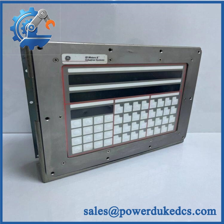
GE DS2020PDMAG6
Quality Assurance & Testing SOP
The should be handled as a controlled power-distribution assembly. Pre-shipment verification should establish the exact identity, physical condition, fuse configuration, power-path integrity, and applicable diagnostic behavior.
- OEM anti-counterfeit visual inspection: Verify GE identification, complete part number, revision information, connector designations, fuse holders, terminal markings, enclosure condition, and PCB/component layout against reference documentation.
- Physical condition inspection: Check terminals, connectors, fuse clips, wiring interfaces, mounting hardware, PCB assemblies, insulation barriers, and enclosure surfaces for corrosion, contamination, impact damage, heat discoloration, or unauthorized modification.
- Part-number and serial recording: Photograph the actual identification label and record all available serial and revision information.
- Power-on self-test (POST): Energize the unit through an appropriate controlled test arrangement and inspect expected startup behavior and available diagnostic indications; where the installed Mark VI test setup exposes controller status, verify normal RUN/ERR behavior.
- AC input verification: Confirm the configured AC input path corresponds to the required 115 VAC or 230 VAC installation before applying power.
- DC distribution testing: Measure applicable 125 VDC distribution points under controlled conditions and record voltage readings.
- Fuse-circuit testing: Check fuse continuity, holder integrity, and circuit isolation for the applicable fuse groups.
- I/O load testing: Apply approved simulated loads to representative downstream circuits and verify stable power delivery.
- Diagnostic-path testing: Verify applicable PDM diagnostic signals and connections through the designated Mark VI interface path.
- Thermal observation: Monitor for abnormal temperature rise, smell, noise, arcing, or current imbalance during energized testing.
- Final QC release: Retain actual-unit photographs, measured values, fuse configuration, revision data, and inspector sign-off with the shipment record.
Procurement & Lifecycle FAQ
Is the GE genuinely in stock and what is the cutoff for emergency shipping?
Physical inventory should be confirmed against the actual module before the PO is released. Current supplier references list inventory, but emergency dispatch depends on the specific unit completing inspection and packing before the carrier cutoff.;
How do you guarantee the condition and authenticity of an obsolete or surplus ?
The quotation should clearly state New Surplus, Factory Stock, Rebuilt, or another defined condition. Request actual-unit photographs, complete part-number verification, serial/revision records, electrical inspection results, and the pre-shipment QC report.
Are there any firmware compatibility issues engineers should warn about before issuing the PO?
Firmware flashing is not the main compatibility concern for this power-distribution module. Engineering should verify the cabinet type, AC source selection, 125 VDC distribution, connector destinations, fuse ratings, and diagnostic wiring. GE documentation distinguishes the interface-cabinet and controller-cabinet PDM arrangements.
Can be hot-swapped while the turbine is operating?
It should not be treated as a hot-swappable field device. The PDM distributes control-system power across multiple circuits, so replacement planning should include proper isolation, shutdown procedures, verification of zero hazardous voltage, and controlled re-energization. The actual plant procedure must follow the site’s approved electrical safety documentation.
What are the warranty terms and return policies?
The quotation and PI should state the warranty period, coverage scope, exclusions, and return-authorization process. For a legacy PDM, the documentation should also distinguish pre-shipment defects from damage caused by incorrect wiring, incorrect fuse selection, improper AC input configuration, unauthorized modification, or installation outside the approved cabinet configuration.











 Start Chat


