

Description
- Brand: GE General Electric
- Full Model Number: DS215DMCBG1AZZ03A
- Lifecycle Status: Legacy / Obsolete Mark V-era hardware
- Core Function: IOS main control and processor/communication card
- Top 3 Technical Specs: Intel 80C186 at 33 MHz; Intel 80C196 at 15.667 MHz; DLAN and DLAN+ ARCNET communications
- Control Power: 19 V AC center-tapped control power supplied through the associated auxiliary power arrangement
- Interfaces: Operator keypad/display; DLAN; DLAN+; RS-232C; optional Genius LAN; local I/O; DS200IOEA interface
- Assembly: DS215 upgraded Mark V hardware
- Firmware: Firmware-bearing assembly; exact programmed set must match site application
- Manual Reference: GEH-6122
- Approx. Weight: 2 lb listed by a current specialist source
- Stock & Condition: Specialist legacy stock; unused and rebuilt conditions reported; confirm exact lot before PO
- Emergency Shipping: Same-day dispatch reported by a current specialist supplier, subject to physical-stock and carrier cutoff confirmation
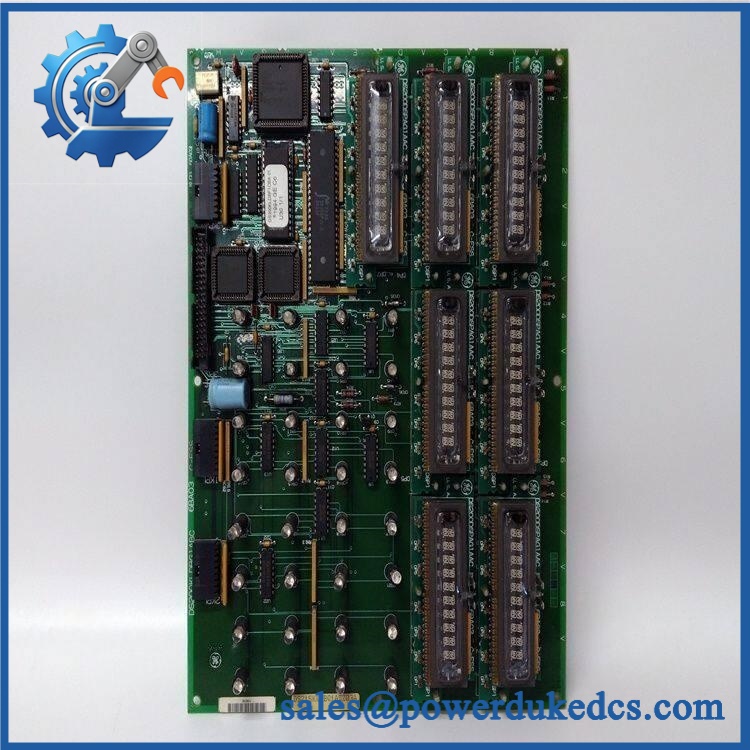
The DS215DMCBG1AZZ03A is identified as an IOS Processor and Communication Card for GE Speedtronic control equipment. Documentation for the DMCB architecture identifies it as the main control board for IOS, IOS+, and IEI units, handling control-power distribution together with processor and communication functions.
Obsolescence & Supply Chain Deep Dive
When an installed GE IOS control unit loses its DMCB, the outage impact can extend well beyond one failed PCB. The board sits at the center of several information paths, including the operator interface, DLAN, optional ARCNET-based DLAN+, RS-232C, optional Genius LAN, local logic I/O, and the DS200IOEA expansion interface. GE documentation identifies the DMCB as the IOS Main Control Board, while current specialist listings identify DS215DMCBG1AZZ03A as an IOS processor and communication card with firmware. That makes exact revision and programmed-device verification important before the replacement is released for shipment.
From a TCO standpoint, a validated replacement can preserve the existing IOS/Mark V architecture without forcing a wider control-platform migration. The financial benefit becomes significant when the installed equipment remains serviceable and the main exposure is the availability of one obsolete controller board. A properly matched surplus or rebuilt DS215 can avoid cabinet redesign, application redevelopment, broader I/O changes, and extended commissioning work associated with a system replacement. —Lead time can still vary according to firmware configuration, test requirements, and physical stock. The purchase record should therefore capture the exact DS215DMCBG1AZZ03A identifier, firmware-bearing configuration, revision data, and intended IOS application.
Compatibility & Replacement Matrix
| Procurement / Engineering Item | Assessment |
|---|---|
| Replacement Classification | Conditional Drop-in Replacement |
| Primary Application | GE IOS / IOS+ / IEI control units within compatible Mark V-era architectures |
| Main Function | Control power management plus processor and communication functions |
| Processor 1 | Intel 80C186, 33 MHz |
| Processor 2 | Intel 80C196, 15.667 MHz |
| Communication | DLAN, DLAN+ ARCNET, RS-232C, optional Genius LAN |
| Firmware Flash Required | Usually no field flash when the supplied firmware set matches the installed application |
| Firmware Verification | Mandatory before installation |
| Hardware Modification | Normally none for a correctly matched board |
| Backplane Interface | Required; board interfaces with associated IOS hardware rather than acting as a standalone field-I/O module |
| Typical Replacement Time | Approximately 2–4 labor hours for isolation, board replacement, configuration review, startup, and communication checks |
| Budgetary Field Labor | Approximately USD 300–1,000 excluding outage costs and specialist commissioning |
| Commissioning Requirement | Processor startup, diagnostic verification, operator-interface test, LAN communication test, and application-level confirmation |
Field Traps
Firmware mismatch:
The suffix AZZ03A is associated with a specific hardware and firmware configuration. Current supplier documentation describes the unit as a firmware-bearing card, while other technical references identify socketed PROM/EEPROM devices. Do not approve a replacement only because the PCB shape and connector arrangement appear identical. The programmed memory set must be checked against the installed application.
DS200 versus DS215 architecture:
The DS215 designation represents a later Mark V hardware generation built from the earlier DS200 architecture. GE’s documentation also notes that board part numbers encode assembly and revision information, and factory substitutions may occur based on availability and design changes. For a field replacement, compare the complete board number and application documentation instead of assuming that every DS200 DMCB variant is interchangeable with every DS215 version. ([turn562849view0]citeturn562849view0)
Communication network configuration:
DLAN and DLAN+ are not generic Ethernet replacements. GE documents DLAN+ as an ARCNET-based network, with specific topology and termination requirements. In an EX2000 environment, the documented ARCNET network uses RG-62A coaxial cable, 2.5 MBaud signaling, and 93-ohm termination at the ends of the daisy chain. A controller-board swap should therefore include a network-level verification rather than only a power-on check. ([turn122324view0]citeturn122324view0)
- GE DS215DMCBG1AZZ03A
Quality Assurance & Testing SOP
A firmware-bearing DS215DMCBG1AZZ03A should pass a controlled inspection sequence before shipment. The acceptance standard should cover identity, firmware configuration, processor startup, communications, and board-level physical condition.
OEM anti-counterfeit visual inspection
Verify the complete GE part number, DS215 assembly designation, DMCB identification, revision markings, connector geometry, PCB construction, component population, socketed memory devices, solder condition, and board finish. Capture photographs of the identification label and both PCB sides.
Firmware and memory verification
Inspect all socketed PROM/EEPROM positions that are part of the supplied configuration. Record the installed device identifiers and compare them with the customer’s requested firmware or original-board data when available. A board supplied without the expected memory devices should not be represented as a ready-to-install firmware-bearing assembly.
Power-on self-test
Install the board only in a suitable controlled test setup. Apply the specified control power through the approved IOS test arrangement and observe startup behavior. Confirm processor initialization and the host-system diagnostic indications. Record any ERR, RUN, fault, or abnormal initialization state before proceeding.
Processor functional test
Verify operation of the primary and LAN processor functions using the applicable test environment. The documented DMCB architecture uses an 80C186 at 33 MHz for the dominant processor and an 80C196 at 15.667 MHz for LAN processing. ([turn723100view0]citeturn723100view0)
Communication testing
Exercise the relevant DLAN and DLAN+ communication paths under controlled conditions. Where the application uses ARCNET, verify network participation, node communication, and expected link behavior. RS-232C functionality should also be checked where fitted or required by the application.
Operator interface test
The DMCB supports the operator keypad/display path. Verify communication with the associated keypad/display hardware and confirm that expected data and diagnostic information can be presented. GE documentation identifies the KLDB and DKLB families as operator-interface options using their own keyboard microprocessor architecture. ([turn723100view0]citeturn723100view0)
I/O interface testing
Where the test fixture includes optional local I/O or DS200IOEA expansion hardware, exercise representative interface points and confirm stable communication under simulated load. A basic continuity test alone does not establish processor or network functionality.
Control-power verification
The documented DMCB arrangement receives 19 V AC center-tapped control power through the associated auxiliary power module. Confirm that the test environment supplies the intended power arrangement and that the board’s control-power circuitry behaves normally before full functional testing. ([turn723100view0]citeturn723100view0)
ESD and packing control
Handle the PCB in an ESD-controlled area. Protect socketed memory, connector pins, board edges, and mounted components with antistatic packaging and mechanical cushioning.
Final QC release
The shipment file should contain the exact part-number record, revision photographs, firmware/memory record, startup-test result, communication-test result, visual inspection report, and packing photographs. Test videos can be retained when the buyer requires evidence for critical-spare approval.
Procurement & Lifecycle FAQ
Is available for emergency shipment?
A current specialist supplier lists as in stock and available for same-day shipment, with both unused and rebuilt conditions reported. That is supplier-specific inventory information, not a guarantee of continuous market availability. Emergency buyers should confirm the physical unit, exact condition, firmware configuration, and carrier cutoff immediately before the PO is released. ([turn723100view0]citeturn723100view0)
How do you verify the condition and authenticity of an obsolete board?
The procurement record should identify the complete number, visible revision markings, memory-device configuration, connector condition, PCB photographs, and functional-test status. For critical applications, request processor startup evidence and DLAN/ARCNET communication results in addition to a visual inspection. An unused board and a rebuilt board should be quoted as different conditions.
Does the require a firmware flash?
Not necessarily. This part is commonly supplied as a firmware-bearing assembly, so the first question is whether the installed PROM/EEPROM set already matches the customer’s application. If the correct firmware is present, a separate field flash may not be required. Engineers should still verify the firmware/device identifiers before commissioning. ([turn924776search1]citeturn924776search1) ([turn924776search2]citeturn924776search2)
Is this a direct replacement for every GE DMCB board?
No. Treat it as a conditional drop-in replacement. The IOS generation, complete part number, hardware revision, firmware set, communications configuration, and associated boards must be checked. GE documentation identifies the DMCB as the IOS Main Control Board, while the variant represents a later hardware implementation within the same broader Mark V-era architecture. ([turn562849view0]citeturn562849view0)
What warranty and return terms should be specified in the PO?
State the exact part number and revision, supplied condition, firmware status, functional-test scope, warranty period, DOA definition, return authorization process, and responsibility for approved return freight. For obsolete industrial electronics, these commercial details should be fixed in the quotation because warranty coverage can differ between unused, surplus, rebuilt, and repaired units.











 Start Chat


