

Description
- Brand: GE / GE Fanuc
- Full Model Number: ENK32
- Lifecycle Status: Legacy / Obsolete
- Core Function: High-speed counter and discrete-input interface for GE Series 90-30 PLC systems
- Top 3 Technical Specs: 2 isolated high-speed counter channels; up to 100 kHz per channel; 5–30 VDC input range
- Counting Modes: Up/down; quadrature A/B; pulse + direction
- Isolation: 500 VDC field-to-logic isolation
- Form Factor: Single-slot Series 90-30 I/O module
- Configuration: DIP-switch based hardware configuration
- Stock & Condition: New Surplus / Tested Surplus / Tested Refurbished subject to physical-unit confirmation
- Shipping: Emergency dispatch subject to confirmed stock and carrier cutoff
Current secondary technical references identify GE ENK32 as a legacy high-speed counter/discrete-input module for the GE Series 90-30 PLC platform. One published specification lists two isolated high-speed counter channels, a maximum input frequency of 100 kHz per channel, 5–30 VDC field input capability, several counting modes, 500 VDC isolation, and a single-slot 90-30 form factor.
Obsolescence & Supply Chain Deep Dive
The maintenance problem with an ENK32 failure is usually not the physical installation work. It is finding the exact legacy module with the required counter characteristics before the production asset reaches an extended outage. The ENK32 is associated with GE Series 90-30 installations and is described as a high-speed counter interface for pulse-generating field devices such as encoders and flow-related instrumentation. Its documented two-channel architecture and 100 kHz-per-channel capability make exact model verification important when replacing a failed module. For procurement teams, the practical objective is to secure a verified spare while the installed Series 90-30 system is still operating and its original configuration can be documented.
The TCO case is based on targeted replacement rather than premature control-system migration. Keeping an existing Series 90-30 installation in service can avoid the engineering effort associated with rack replacement, logic conversion, I/O rewiring, field-device validation, and commissioning. A same-model ENK32 replacement can preserve the existing counter application and associated field wiring, provided the replacement’s hardware configuration matches the installed unit. That configuration point matters: published references specify DIP-switch setup and multiple counting modes, so the spare should be checked against the failed unit’s documented settings before installation.
Compatibility & Replacement Matrix
| Buyer Review Item | ENK32 Assessment |
|---|---|
| Exact-Part Replacement | Drop-in Replacement for an existing GE installation, subject to configuration verification |
| System Family | GE Series 90-30 PLC |
| Core Function | Dual-channel high-speed counter / discrete-input interface |
| Input Channels | 2 isolated counter channels |
| Maximum Input Frequency | Up to 100 kHz per channel |
| Input Voltage | 5–30 VDC |
| Counting Modes | Up/down; quadrature A/B; pulse + direction |
| Firmware Flash | No software firmware-flash requirement identified in the available technical reference |
| Hardware Modification | Normally not required for an exact same-model replacement |
| Configuration Work | Required; verify DIP-switch settings before startup |
| Installation Labor | Approximately 1–3 hours for controlled replacement and configuration verification |
| Functional Verification | Approximately 2–4 hours depending on encoder, pulse-source, and PLC test access |
| Cross-Model Substitution | Engineering approval required before using another high-speed counter module |
Field Traps to Watch Out For
DIP-switch configuration mismatch: The published reference specifies hardware configuration through DIP switches. A replacement with incorrect counting-mode or channel settings can appear electrically normal while producing incorrect pulse counts. Record the original switch positions before removing the failed unit.
Input-level mismatch: The documented input range is 5–30 VDC. Confirm that the connected encoder, pulse transmitter, or other field source operates within the required electrical range before connecting the replacement. Do not assume that a similar-looking counter module has the same input characteristics.
Channel isolation requirements: The available specification identifies two isolated high-speed counter channels with 500 VDC field-to-logic isolation. The field wiring arrangement should therefore be checked against the installed application rather than copied from a different 90-30 counter module.
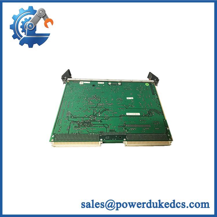
GE ENK32
Quality Assurance & Testing SOP
Part-number verification: Confirm the physical module marking as and record manufacturer, revision, serial number, and all visible identification labels. A model-number discrepancy stops the inspection.
OEM anti-counterfeit visual inspection: Compare the housing, PCB construction, labeling, terminal arrangement, component population, connector geometry, and board markings against the verified GE reference. Any inconsistent marking, unexplained rework, or altered label requires manual review.
Mechanical inspection: Examine the enclosure and connector area for cracks, deformation, contamination, corrosion, bent contacts, damaged retaining hardware, and evidence of previous overheating.
Connector inspection: Check every field and backplane connection for oxidation, damaged contacts, contamination, loose hardware, or mechanical stress. Record the condition before power testing.
Configuration capture: Photograph and document every DIP-switch position before modifying the board. Preserve this record with the QA report so the replacement can be configured against the installed unit.
Power-on self-test (POST): Install the module in an approved GE Series 90-30 test rack and apply controlled power. Verify expected startup behavior and record the actual status indications present on the hardware.
Counter input testing: Apply controlled pulse signals to both counter channels using a calibrated test source. Test representative frequencies within the documented operating range and compare the module’s reported counts with the reference signal. Verify that channel response remains stable under repeated cycles.
Mode verification: Exercise the configured counting mode using an appropriate test source. Where supported by the test fixture, verify up/down, quadrature, and pulse-direction operation against the configured switch state.
I/O load testing: Run both counter channels under representative pulse activity and monitor for missed counts, unstable channel status, unexpected resets, or communication faults.
Isolation check: Where the laboratory fixture permits, verify the specified isolation characteristics using an appropriate calibrated electrical test method and applicable internal safety procedure.
Final QA release: Record exact model, manufacturer marking, revision, serial number where available, DIP-switch configuration, POST result, channel-by-channel test results, test frequency, technician, and test date. Approved units are handled with ESD protection and mechanical packaging suitable for shipment.
Procurement & Lifecycle FAQ
Is the GE genuinely in stock and what is the cutoff for emergency shipping?
Secondary industrial references currently list units as available for purchase, but online listing status should not be treated as proof of physical stock for a specific supplier. Confirm the actual quantity, condition, manufacturer marking, warehouse location, and carrier cutoff before releasing an emergency PO.
How do you verify the condition and authenticity of an obsolete ?
The acceptance process should include exact model verification, manufacturer and revision inspection, PCB or housing examination, connector inspection, DIP-switch documentation, controlled power-up, and two-channel counter testing. Commercial condition should be stated clearly as New Surplus, Tested Surplus, or Tested Refurbished.
Are there any firmware compatibility issues engineers should review before issuing the PO?
No routine firmware-flash procedure is identified in the available technical reference. The principal compatibility checks are hardware configuration, input voltage, counting mode, channel arrangement, and the requirements of the installed Series 90-30 application.
Is the a direct replacement for an installed unit?
An exact replacement can generally be treated as a board-level drop-in replacement when installed in the corresponding Series 90-30 application. Engineering should still verify the original DIP-switch configuration, field-device voltage, counting mode, and channel wiring before startup.
What warranty and return terms should procurement require?
The PO should specify the exact model, manufacturer marking, revision where applicable, condition category, inspection status, warranty duration, DOA definition, return period, and return-freight responsibility. For obsolete counter modules, retain the supplied unit’s identification photographs and test report with the procurement record.











 Start Chat


