

Description
- Brand: GE General Electric
- Full Model Number: EX2100
- Lifecycle Status: Legacy generation / superseded by EX2100e
- Core Function: Generator excitation control and automatic voltage regulation
- System Type: Static thyristor excitation control system
- Top 3 Technical Specs: Digital regulator control; SCR/thyristor power conversion; simplex or redundant control architecture
- Generator Applications: Steam; gas; hydro
- Control Feedback: Generator terminal voltage; generator current; reactive-power-related signals
- Communications: Ethernet LAN / Unit Data Highway
- Configuration Tools: GE Control System Toolbox
- Stock & Condition: System, cabinet, controller, and replacement assemblies subject to configuration-specific confirmation
- Shipping: Component-level dispatch may be possible; complete-system logistics require project review
The GE EX2100 is a complete generator excitation control system rather than a single standardized PCB or plug-in module. GE’s original EX2100 documentation describes a modular static excitation system that controls generator terminal voltage and reactive volt-amperes through controlled field excitation current. The architecture can use single or multiple power bridges, warm-backup bridges, and simplex or redundant control configurations. It was designed for steam, gas, and hydro turbine-generator applications.
Obsolescence & Supply Chain Deep Dive
The procurement risk with EX2100 is different from that of a discrete Mark V DS200 board. A plant may have an EX2100 installed for many years while individual control boards, I/O assemblies, power-conversion components, keypad assemblies, and other renewal parts become difficult to source. The original EX2100 architecture uses dedicated control, power-conversion, protection, auxiliary, and diagnostic sections, with Ethernet-based communication to associated GE equipment and the operator interface. A maintenance purchase therefore needs to identify the failed assembly, system configuration, ratings, and revision rather than treating “” as sufficient information for a one-for-one hardware order.
The TCO decision depends on whether the objective is targeted life extension or migration to a newer control platform. Replacing one failed assembly while retaining the existing excitation cabinet and power-conversion equipment can avoid the engineering, wiring, commissioning, and outage work associated with a complete system replacement. At the same time, GE Vernova currently positions EX2100e as its newer excitation-control platform and offers control-only retrofit approaches that can retain existing power-conversion sections. For an aging installation, procurement should therefore compare the immediate spare requirement with the remaining asset life and the longer-term cost of a controls migration.
Compatibility & Replacement Matrix
| Buyer Review Item | Assessment |
|---|---|
| Product Classification | Complete excitation-control system / platform rather than a single replacement module |
| Primary Application | Generator excitation and automatic voltage regulation |
| Excitation Type | Static thyristor/SCR excitation |
| Generator Types | Steam, gas, and hydro |
| Control Architecture | Simplex or redundant configurations; system-dependent |
| Power Conversion | Single or multiple bridges; warm-backup configurations available |
| Communications | Ethernet LAN / Unit Data Highway |
| Configuration Software | GE Control System Toolbox |
| Firmware Flash | Configuration-specific; controller hardware and software revision must be verified |
| Hardware Modification | Not applicable to the system as a generic drop-in item; exact assembly determines replacement scope |
| Replacement Class | Not a generic drop-in replacement when “” is the only identification supplied |
| Planning Labor | Approximately 4–8 engineering hours for identification and component-level replacement planning |
| Full Retrofit Labor | Project-specific; controls-only or complete-system migration can require design, installation, testing, and commissioning |
| Migration Path | EX2100e controls modernization is an established GE Vernova option for applicable legacy systems |
The original documentation describes a modular architecture with control modules, a power conversion module, auxiliary equipment, field-flashing and de-excitation functions, protection circuits, and a local diagnostic keypad. This means the exact failed assembly should be identified before approving any replacement.
Field Traps to Watch Out For
System-level model ambiguity: “” does not identify the installed controller board, I/O terminal board, power bridge, keypad, or auxiliary assembly. Procurement should request the complete GE part number from the failed component, cabinet drawing reference, hardware revision, and system rating.
Controller revision mismatch: The uses digital regulator control, and configuration is handled through GE Control System Toolbox. A replacement controller should therefore be checked against the installed application, software/configuration revision, communications architecture, and redundancy arrangement before startup.
Bridge-rating mismatch: configurations can use different numbers of power bridges and different redundancy arrangements. A controller replacement that is correct for one system configuration cannot automatically be assumed suitable for another.
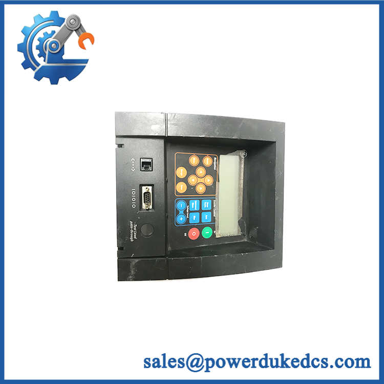
GE EX2100
Quality Assurance & Testing SOP
System identification: Confirm from the cabinet nameplate and identify the actual replacement assembly by its GE part number. Record ML number, serial number, hardware revision, software/configuration revision, and cabinet location where available.
OEM anti-counterfeit visual inspection: Inspect board markings, GE identification labels, connector geometry, PCB construction, component population, and revision markings against the approved hardware record. Any unexplained relabeling, component substitution, or rework receives engineering review.
Mechanical and connector inspection: Check backplane and field connectors, terminal hardware, mounting points, ribbon cables, and cabinet interfaces for oxidation, cracked solder joints, mechanical damage, contamination, or heat exposure.
Power-on self-test (POST): Install the verified replacement assembly in the correct test configuration and apply controlled power. Check power-up sequencing, processor/controller initialization, diagnostic indications, and abnormal fault messages.
Control signal simulation: Apply controlled generator-voltage, current, frequency, and related feedback signals through the approved excitation test fixture. Confirm that the controller responds within the documented application limits.
AVR functional testing: Verify automatic voltage-regulator response using a controlled simulator or approved generator/excitation test setup. Test representative voltage-reference changes, feedback response, limiter operation where supported, and return to stable regulation.
Protection testing: Exercise applicable over-excitation, under-excitation, V/Hz, loss-of-sensing, and related protection functions according to the installed configuration and authorized test procedure. Do not infer available functions solely from the generic system name.
Power-conversion interface testing: Confirm controller-to-bridge command and feedback paths where the replacement assembly participates in the power-conversion control loop. Monitor firing/control signals and diagnostic status under controlled conditions.
Redundancy testing: For redundant configurations, verify active/standby controller behavior and controlled transfer where the test system permits it. Record synchronization and transfer results.
Communications testing: Verify Ethernet/Unit Data Highway communication with the applicable GE control equipment, HMI, and engineering workstation. Check device recognition, parameter access, event reporting, and stable communication.
Final QA release: Record exact replacement part number, configuration, revision data, test fixture, POST result, AVR test result, protection-test result, communications result, technician, and test date. Store the unit using ESD protection and mechanical packaging appropriate for industrial electronics.
Procurement & Lifecycle FAQ
Is the genuinely in stock and what is the cutoff for emergency shipping?
Because is a system family rather than one universal spare part number, stock must be confirmed against the specific failed assembly. A request should include the cabinet/system configuration, exact GE part number, revision, quantity, and destination. Component-level emergency dispatch is a different procurement transaction from shipping a complete excitation cabinet.
How do you verify the condition and authenticity of an obsolete component?
Require photographs of the actual nameplate and PCB or assembly markings before PO approval. The acceptance process should include exact GE part-number verification, revision capture, connector inspection, controlled power-up, functional testing, and a written test report. Commercial condition should be stated as New Surplus, Tested Surplus, or Tested Refurbished.
Are there firmware compatibility issues engineers should review before issuing the PO?
Yes. The issue is configuration rather than assuming that every installation uses identical software. Engineers should verify controller hardware revision, application/configuration revision, communication setup, redundancy arrangement, and the installed generator/excitation configuration before installing replacement control hardware. The original architecture uses GE Control System Toolbox for configuration.
Is the a direct replacement for an installed unit?
itself is not enough information to classify a replacement as a drop-in unit. An exact component-level GE part-number match may support a board-level replacement, subject to revision and configuration checks. A transition from an older installation to EX2100e is a controls modernization project rather than a simple plug-in replacement. GE Vernova documents controls-only retrofit options that can retain existing power-conversion equipment where applicable.
What warranty and return terms should procurement require?
The PO should identify the exact GE assembly part number, hardware revision, condition, test status, warranty duration, DOA definition, return period, and return-freight responsibility. For an system, also document the system rating and configuration because accepting the wrong controller or power-conversion assembly can create a much larger commissioning and outage cost than the original spare purchase.











 Start Chat


