

Description
- Brand: GE Multilin
- Full Model Number: F650BFBF2G0HIE
- System/Series Family: Multilin F650 Feeder Protection and Bay Controller
- One-Sentence Core Function: Digital protection, automation, control, metering, and feeder bay management in one relay platform
- Top 3 Hardcore Specs: Basic LCD display; 24–48 VDC auxiliary supply; 10/100Base-T Ethernet communication
- Stock Status: New Surplus / Fully Tested Refurbished — actual hardware configuration verified before shipment
Module 3: Commercial-Technical Deep Dive
A feeder trip becomes a longer outage when the replacement relay does not reproduce the original protection and communication architecture. The GE Multilin F650 is built for feeder protection, automation, and bay control, combining protection elements, breaker control, metering, event recording, waveform capture, programmable logic, and communications in a single platform. GE identifies the F650 for feeder and related applications, including ring-bus, double-breaker, and breaker-and-a-half arrangements. Its protection suite covers phase, neutral, ground, and sensitive-ground overcurrent; directional functions; voltage and frequency protection; breaker failure; autoreclosing; synchronism check; and CT/VT supervision.
This exact order code matters because F650 units are configured by hardware option code rather than being a single universal relay. GE’s ordering documentation shows the code structure differentiates display, communication boards, I/O boards, auxiliary voltage, and sensing options. For this unit, the published code identifies a basic display, 10/100 Base-T Ethernet, and a 24–48 VDC auxiliary supply range with a stated operating range of 19.2–57.6 VDC; the exact CT/VT and I/O configuration should still be checked against the nameplate before installation. That distinction can prevent a costly panel retrofit: the F650 also uses modular construction and supports field firmware upgrades through EnerVista 650 Setup.
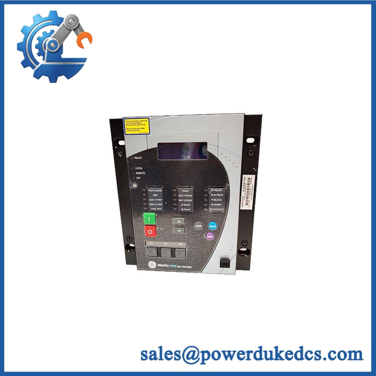
GE F650 F650BFBF2G0HIE
Module 4: Compatibility & Installation Traps
Migration/Compatibility
- Replacement status: Configuration-specific replacement. Do not order by “F650” alone; match the complete F650BFBF2G0HIE code and physical identification label.
- Firmware requirement: A like-for-like hardware replacement does not automatically require a firmware flash. However, GE documentation shows that hardware and firmware revisions are closely tied to supported features and EnerVista Setup versions, so the existing firmware should be recorded before replacement.
- Settings migration: Back up protection settings, FlexLogic equations, communications parameters, and I/O assignments before removing the existing relay. A replacement unit may power up correctly while still being functionally uncommissioned.
- Logic rewrite: A same-configuration replacement normally does not require a protection-logic rewrite, but every programmed input, output, trip path, interlock, and communications point should be validated during commissioning.
⚠️ Field Traps (Watch Out)
- Auxiliary-power mismatch: The published ordering table identifies LO as 24–48 VDC, with a permitted range of 19.2–57.6 VDC, while HI is a different high-voltage supply option. Do not assume all relays share the same control-power input.
- Communication option mismatch: The order code separately defines rear serial and rear Ethernet communication boards. A replacement containing a different communication option can create an immediate SCADA integration problem even when the front-panel relay appears identical.
- CT/VT configuration: Confirm the current-input and voltage-input ratings from the actual unit label and site drawings before applying secondary injection. Protection settings cannot compensate for a fundamentally incorrect input configuration.
- Drawout handling: The uses modular construction, and GE documentation specifically includes procedures for module withdrawal and communication-board withdrawal/insertion. De-energize the equipment and follow the applicable GE procedure rather than treating the relay as a live plug-in device.
Module 5: Quality Assurance SOP
Our pre-shipment inspection for a GE F650BFBF2G0HIE should verify the actual hardware configuration, not just the external case:
- OEM anti-counterfeit visual inspection — verify GE Multilin markings, identification, order-code label, revision information, PCB construction, terminal blocks, communication interfaces, and display assembly.
- Order-code verification — confirm F650BFBF2G0HIE against the unit nameplate and inventory record.
- Hardware-option inspection — identify the installed display, communication, I/O, auxiliary-power, and measurement hardware before release.
- Power-input verification — controlled application of the correct auxiliary supply; monitor startup current and check for abnormal heating or diagnostic indications.
- Power-on self-test (POST) — check LCD initialization, status LEDs, keypad response, diagnostic state, and startup messages.
- Protection-input verification — where test equipment permits, perform secondary-injection checks on representative current and voltage inputs and confirm the measured values against configured ratios.
- Digital I/O testing — energize representative binary inputs and verify programmed output transitions under controlled test conditions.
- Breaker-control path verification — where the test setup supports it, check trip/close logic, breaker-status inputs, and programmed interlocks without connecting to a live breaker.
- Communication handshake verification — verify Ethernet communication and the configured protocol path supported by the actual communication board; confirm stable session establishment and valid data exchange.
- Metering and recording check — confirm representative voltage, current, frequency, power, event logging, and waveform-recording functions where supported by the installed configuration.
- Firmware and configuration record — record firmware revision, serial number, hardware code, and available configuration information before packaging. GE documentation identifies firmware versions alongside EnerVista Setup versions, making this record important for replacement planning.
- Final ESD packaging — antistatic protection, mechanical cushioning, terminal protection, and moisture control applied before shipment.
GE’s own documentation includes an inspection checklist, safety procedures, modular hardware architecture, communications procedures, and firmware-management procedures. That makes configuration traceability a more useful QA checkpoint than a simple “powers on” inspection.
Module 6: CRO-Driven Buyer FAQ
1. Is the GE obsolete, and is F650BFBF2G0HIE still a valid configuration?
The remains an active GE product family in current support documentation, although specific hardware and communication options have reached end-of-manufacturing status. GE’s resource center lists recent release documentation and multiple end-of-manufacturing notices for particular communication and option groups. That makes the complete order code more important than the family name when sourcing a replacement.
2. Can I hot-swap the ?
Do not treat the as a routine live-service plug-in relay. GE documentation contains explicit procedures for module and communication-board withdrawal/insertion, along with electrical safety instructions. Follow the plant’s approved shutdown and LOTO procedure and the applicable GE maintenance procedure before removing the unit.
3. What auxiliary supply does F650BFBF2G0HIE use?
The published ordering documentation identifies the LO auxiliary-voltage option as 24–48 VDC, with an operating range of 19.2–57.6 VDC. Verify the actual nameplate before energization because models are available with different auxiliary-power options.
4. Does this configuration support Ethernet communications?
Yes. The ordering table identifies a B option for 10/100 Base-T Ethernet in the rear Ethernet communication-board position. The broader platform supports serial and Ethernet communications and multiple power-system protocols depending on the installed hardware and software configuration.
5. What warranty and technical support should I expect?
Warranty duration should be stated on the quotation for the exact unit supplied. Technical support should cover part-number verification, hardware-option matching, firmware identification, terminal interpretation, configuration review, and documented pre-shipment test results. It should not be represented as a substitute for protection coordination, CT/VT engineering, site commissioning, or electrical safety procedures.











 Start Chat


