

Description
- Brand: GE / GE Fanuc-compatible
- Full Model Number: HE700GEN200C
- Lifecycle Status: Legacy / Obsolete
- Core Function: Dual-channel Genius bus interface for VME-based control systems
- Top 3 Technical Specs: 2 Genius channels; single-slot VME module; 38.4K / 76.8K / 153.6K baud configuration
- Network Type: GE Genius fieldbus
- Genius Bus Address: 0–31
- VME Installation: Single slot
- Configuration: Six DIP-switch groups covering Genius setup, interrupts, I/O address, memory address, and operating mode
- Genius Outputs at Startup: DIP-switch selectable
- Typical Bus Termination: 120 Ω when cable impedance is unknown
- Stock & Condition: New Surplus / Tested Surplus / Tested Refurbished subject to physical-unit confirmation
- Shipping: Emergency dispatch subject to confirmed stock and carrier cutoff
The HE700GEN200C is documented as a dual-channel uGENI VME interface module used with GE Fanuc Genius communications. The underlying HE700GEN200/100 manual identifies the 200 version as a single-slot generic VME module and states that it can replace or operate alongside a Genius Bus Controller. It provides two independently configured uGENI channels, with Genius bus address settings from 0 through 31 and selectable communication rates of 38.4K, 76.8K, and 153.6K baud in the documented modes.
Obsolescence & Supply Chain Deep Dive
A failed HE700GEN200C can interrupt a legacy VME control architecture even when the PLC CPU and Genius field devices remain operational. This module sits between the VME environment and Genius networks, so sourcing a visually similar communication card is not enough. The documented design uses two uGENI channels, configurable VME addressing, interrupt settings, Genius addresses, and separate communication-rate settings for each channel. Up to 32 Genius devices can share a bus, with controller addresses typically assigned according to the established network architecture. For maintenance teams, the procurement priority is therefore an exact, identified replacement with the original switch configuration preserved.
From a TCO perspective, a same-model module replacement can avoid a larger controls conversion when the existing VME and Genius architecture remains serviceable. The installed rack, Genius field devices, network cabling, PLC application, and commissioning procedures can remain in place, limiting the intervention to the failed interface and its configuration. The manual specifically requires the VME CPU addressing scheme, interrupt capability, Genius bus address, baud rate, and startup output behavior to be determined before configuring the module. That makes planned spare inventory valuable: a pre-verified unit can reduce outage exposure compared with identifying network settings during an emergency event.
Compatibility & Replacement Matrix
| Buyer Review Item | HE700GEN200C Assessment |
|---|---|
| Exact-Part Replacement | Drop-in Replacement for an existing HE700GEN200C installation after configuration verification |
| System Architecture | VME-based control system with GE Genius fieldbus |
| Module Type | Dual-channel uGENI VME interface |
| VME Form Factor | Single-slot generic VME module |
| Genius Channels | 2 independent channels |
| Genius Address Range | 0–31 per configured bus |
| Baud Rates | 38.4K; 76.8K; 153.6K Standard; 153.6K Extended |
| Firmware Flash | No routine firmware-flash procedure identified in the reviewed manual |
| Hardware Modification | Normally not required for an exact same-model replacement |
| Configuration Work | Required — DIP switches must match the installed VME and Genius architecture |
| VME Interrupts | Configurable through DIP-switch settings |
| Startup Output Control | DIP-switch selectable |
| Planned Replacement Labor | Approximately 1–3 hours |
| Network Verification | Approximately 2–4 hours depending on field-device access |
| Cross-Model Substitution | Engineering approval required |
The manual identifies six DIP-switch groups. Their functions include interrupt priority, Genius setup for each uGENI channel, interrupt mask/user mode, uGENI memory address, and VME I/O address/interrupt vector. The I/O address and interrupt vector are linked to the configured address base, so replacing the physical module without reproducing the original switch settings can prevent the VME master from addressing it correctly.
Field Traps to Watch Out For
Genius address or baud-rate mismatch: Each uGENI channel is configured independently. The original settings for bus address and baud rate must be recorded before replacement. The documented choices include 38.4K, 76.8K, and 153.6K baud, with both Standard and Extended 153.6K modes. A wrong setting can prevent normal network communication even when the VME board powers up normally.
VME address and interrupt mismatch: DIP Switches 1, 4, 5, and 6 participate in interrupt, user-mode, memory-address, and I/O-address configuration. The manual also states that the interrupt acknowledge level must match the configured interrupt level. Verify the existing CPU’s supported address and interrupt scheme before startup.
Network termination error: The Genius network uses Serial 1, Serial 2, Shield In, and Shield Out connections. The manual specifies termination at both ends of the bus and notes 120 Ω resistors when the cable characteristic impedance is unknown. Incorrect termination can create communication faults that may initially appear to be a module failure.
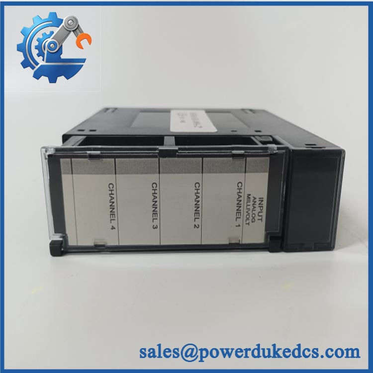
GE HE700GEN200C
Quality Assurance & Testing SOP
Part-number verification: Confirm the physical marking as HE700GEN200C and record manufacturer identification, hardware revision, serial number, and assembly markings. The exact suffix must be documented before testing.
OEM anti-counterfeit visual inspection: Compare the PCB layout, VME connector, Genius interface section, labels, daughterboard markings where present, component population, and board identification against the approved hardware reference. Any inconsistent marking or unexplained rework triggers manual review.
Mechanical inspection: Examine the VME connector, front-panel connector hardware, PCB, mounting points, and enclosure for corrosion, contamination, cracked solder joints, bent contacts, impact damage, and evidence of overheating.
Connector inspection: Check Serial 1, Serial 2, Shield In, and Shield Out connections for damaged or oxidized contacts. Verify cable retention and connector condition before electrical testing.
Configuration capture: Photograph all six DIP-switch groups before changing any settings. Record the Genius address, baud rate, startup output enable, user/supervisor mode, I/O address, memory address, and interrupt configuration.
Power-on self-test (POST): Install the module in an approved VME test rack and apply controlled power. Verify initialization behavior, interface status, communication status, and any diagnostic indications actually available on the hardware.
Genius communication testing: Connect both Genius channels to a controlled test network. Exercise representative devices and confirm bus communication, device recognition, data exchange, and stable operation.
Baud-rate testing: Verify the configured communication rate on each uGENI channel using an approved test fixture. Test the applicable 38.4K, 76.8K, or 153.6K configuration required by the customer’s installation.
Genius bus load testing: Operate representative devices across the configured Genius network and monitor for communication errors, intermittent status changes, missed data, or repeated bus resets. Where the test environment permits, exercise the network near the intended device count and operating load.
VME addressing test: Verify the module responds at the configured I/O and memory address ranges and that the selected interrupt settings align with the test CPU configuration.
Interrupt verification: Exercise the configured VME interrupt function where supported by the test system. Confirm that the interrupt level and acknowledge configuration are consistent with the CPU requirements.
Startup output test: Where the test setup includes output-capable Genius devices, verify the configured startup behavior. The manual provides a DIP-switch selection for enabling or disabling outputs during startup.
Final QA release: Record exact model, revision, serial number where available, all DIP-switch settings, POST result, channel 1 test, channel 2 test, VME addressing result, interrupt test, network test, technician, and test date. Approved units are handled using ESD protection and protective packaging.
Procurement & Lifecycle FAQ
Is the genuinely in stock and what is the cutoff for emergency shipping?
Current industrial inventory listings show units being offered for sale, including listings described as in stock. Real-time physical inventory still needs to be confirmed for the specific supplier, so the PO should identify quantity, exact suffix, physical condition, revision, and required carrier cutoff before payment.
How do you verify the condition and authenticity of an obsolete ?
The inspection should include exact model verification, manufacturer and revision capture, PCB and connector inspection, DIP-switch documentation, controlled VME power-up, dual-channel Genius communication testing, and VME addressing checks. The commercial condition should be identified explicitly as New Surplus, Tested Surplus, or Tested Refurbished.
Are there any firmware compatibility issues I should warn my engineers about before issuing the PO?
No routine firmware-flash procedure is identified in the reviewed uGENI manual. The principal compatibility risks are configuration-related: Genius bus address, baud rate, VME I/O address, memory address, interrupt level, interrupt vector, user/supervisor mode, and startup output behavior.
Is the a direct replacement for an installed unit?
For an existing , an exact same-model replacement can generally be handled as a drop-in replacement at the hardware level. The replacement must still reproduce the approved DIP-switch configuration and be validated on the Genius network and VME backplane before returning the system to operation. The HE700GEN200/100 manual explicitly describes the module as a single-slot VME device that can replace or operate alongside a Genius Bus Controller.
What warranty and return terms should procurement require?
The PO should specify the exact model, hardware revision, condition, test status, warranty period, DOA definition, return window, and return-freight responsibility. The original uGENI manual contains a historical Horner APG warranty for the HE700GEN100/200 family, but that document’s terms apply to its original sales arrangements and should not be presented as the warranty for modern surplus inventory.











 Start Chat


