

Description
- Brand: GE / GE Fanuc
- Full Model Number: IC200ALG327H
- System/Series Family: GE VersaMax Distributed I/O
- Core Function: 12-channel analog voltage output module for PLC and process-control systems
- Resolution: 13-bit
- Output Type: Voltage
- Output Range: ±10.24 VDC or 0 to +10 VDC
- Channels: 12 single-ended channels, one group
- Update Rate: 15 ms
- External Power: Required for field outputs
- Backplane Consumption: 50 mA from +5 V bus
- Status Indicators: FLD PWR, OK
- Mounting: Requires IC200CHSxxx carrier base
- Configuration: Jumper-selected output range and output-hold behavior
- Stock Status: New Surplus / Fully Tested Refurbished — verify exact H revision and carrier compatibility before shipment
GE VersaMax documentation identifies IC200ALG327 as a 13-bit analog voltage output module with 12 channels, supporting ±10 VDC or 0 to +10 VDC operation. The H-suffix unit is marketed as the IC200ALG327H revision of this module. The module requires a VersaMax carrier base and external power for its outputs.
Module 3: Commercial-Technical Deep Dive
A single failed analog output card can stop several control loops at once. The GE IC200ALG327H is a dense VersaMax analog-output module providing 12 single-ended voltage outputs with 13-bit resolution. The documented output range is either ±10.24 VDC or 0 to +10 VDC, while the module’s typical update rate is 15 ms. Intelligent processing is handled by the VersaMax CPU or Network Interface Unit, so this card operates as the field-output layer rather than as an independent programmable controller.
The hard ROI is keeping multiple analog control signals online without replacing the entire VersaMax I/O architecture. Twelve channels in one module can cover valve commands, speed references, actuator signals, drive setpoints, or other analog devices while retaining the existing carrier and PLC configuration. Output range is jumper-configurable, and the carrier also provides the output-hold/default behavior selection. —That configuration must match the installed application: a module set for bipolar output is not automatically equivalent to one commissioned for 0–10 VDC, even though both ranges belong to the same IC200ALG327 family.
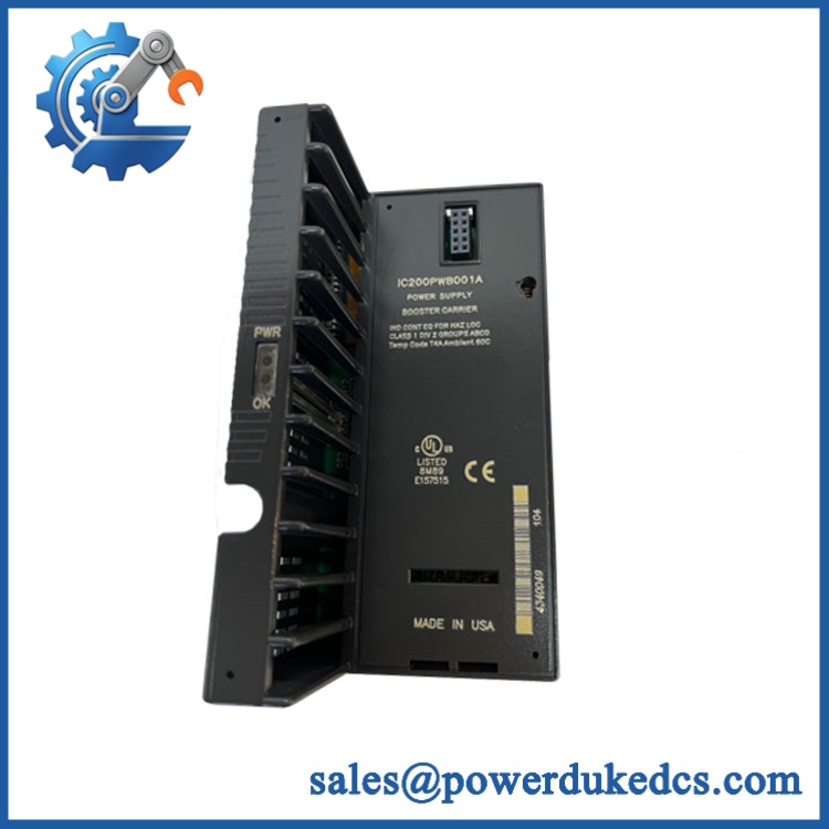
GE IC200ALG327H
Module 4: Compatibility & Installation Traps
Migration/Compatibility
For an existing GE VersaMax installation specified for IC200ALG327H, the preferred strategy is a like-for-like analog output module replacement. The module requires an IC200CHSxxx carrier base, so the carrier, terminal arrangement, and installed firmware/configuration should be verified before installation.
No PLC logic rewrite is normally required solely because the output module is replaced. The commissioning concern is preserving the correct channel mapping, output range, scaling, output-hold behavior, and external field-power arrangement.
⚠️ Field Traps (Watch Out)
- Output-range jumper: The module supports ±10.24 VDC and 0 to +10 VDC configurations. Verify the installed carrier jumper arrangement before applying a replacement. An incorrect range can produce a valid-looking output with the wrong engineering meaning.
- External field power: The module requires an external power source for its outputs. A healthy backplane supply does not, by itself, prove that the field-output section is powered.
- Output-hold configuration: Jumper selection can determine whether outputs retain their last state when module power or communications are interrupted. Record the existing configuration before removal because the behavior can matter for actuators and control valves.
- Carrier compatibility: IC200ALG327H is an I/O module, not a standalone rackless device. Confirm the IC200CHSxxx carrier and terminal wiring before replacement.
- Analog commoning: With 12 single-ended outputs in one group, verify common/reference wiring carefully. Improper field-side commoning can affect multiple channels simultaneously.
Module 5: Quality Assurance SOP
- OEM anti-counterfeit visual inspection — verify GE/GE Fanuc markings, complete IC200ALG327H identifier, terminal layout, LED markings, housing condition, and evidence of unauthorized modification.
- Part-number reconciliation — photograph the full catalog number, revision marking, serial data, and all visible secondary identifiers.
- Mechanical inspection — inspect the module housing, carrier interface, terminals, LED window, and connector surfaces for cracks, oxidation, contamination, or damage.
- Carrier compatibility check — verify the module is tested with an appropriate IC200CHSxxx carrier before functional testing.
- Power-on self-test (POST) — energize the VersaMax assembly and verify OK and FLD PWR indications under the approved test conditions.
- Output-range verification — confirm the installed jumper configuration and test both supported operating modes where the laboratory fixture permits.
- Analog-output accuracy test — command representative output values and measure the resulting voltage with calibrated instrumentation.
- Multi-channel verification — test representative channels across the module and, where required, verify all 12 outputs individually.
- Output-hold test — simulate the documented loss-of-power or communication condition and verify the configured output response.
- Update-rate observation — verify representative command-to-output response against the expected 15 ms update behavior where the test platform supports time-domain measurement.
- Stability observation — operate multiple channels simultaneously and monitor for output drift, channel interaction, resets, or abnormal heating.
- Final QC release — retain module photographs, jumper configuration, measured output values, carrier identification, and packaging inspection records.
For a multi-channel analog output module, a single measured voltage is not enough. Acceptance should establish correct range selection, stable field power, representative channel accuracy, and proper behavior during communication or power interruptions.
Module 6: CRO-Driven Buyer FAQ
1. What is GE ?
It is a GE Fanuc VersaMax analog output module providing 12 voltage-output channels with 13-bit resolution. The documented output ranges are ±10.24 VDC and 0 to +10 VDC.
2. Is an analog input module?
No. It is an analog output module. It sends voltage signals to field devices such as actuators, drives, control valves, or other analog loads.
3. What carrier does use?
The VersaMax documentation states that analog output modules require an IC200CHSxxx carrier base. Verify the exact carrier and terminal arrangement in the installed system before ordering.
4. Can be hot-swapped?
Do not assume hot-swap capability. The module is connected to an active backplane and external field power. Follow the VersaMax maintenance procedure and site isolation requirements before removing or installing the module.
5. Does require PLC programming?
The module itself does not require standalone programming. The VersaMax CPU or Network Interface Unit handles intelligent processing. The replacement still requires correct I/O configuration, channel mapping, output scaling, jumper settings, and application verification.
6. What warranty and technical support should I expect?
The quotation should clearly state whether the module is new surplus, unused, or tested refurbished and specify the warranty duration. Technical support should cover exact-part verification, carrier compatibility, output-range configuration, analog-output testing, and QC records. PLC application changes, loop commissioning, and field troubleshooting should remain separate engineering activities.











 Start Chat


