

Description
- Brand: GE Fanuc / GE
- Full Model Number: IC200ALG620
- System/Series Family: VersaMax Modular I/O
- One-Sentence Core Function: Four-channel RTD analog input module for direct resistance-temperature measurement in VersaMax control systems
- Top 3 Hardcore Specs: 4 RTD channels; 16-bit conversion; 3-wire or 4-wire RTD support
- Input Type: RTD / resistance
- Channels: 4
- Resolution: 15 bits plus sign / 16-bit data format
- RTD Excitation: Supplied by the module
- Supported Sensors: Platinum, copper, nickel, nickel/iron, and configurable resistance inputs
- Wire Configuration: 3-wire or 4-wire
- Update Rate: Approx. 210 ms/channel at 60 Hz; 230 ms/channel at 50 Hz
- Accuracy: Approximately ±0.15% at 25°C for RTD temperature measurement
- Backplane Current: 125 mA maximum at 5 VDC; 125 mA maximum at 3.3 VDC
- Isolation: 250 VAC continuous input-to-logic; 1500 VAC for 1 minute to frame ground
- Channel-to-Channel Isolation: 50 VDC
- Status LED: OK
- Mounting: VersaMax carrier-based installation
- Stock Status: New Surplus / Factory Sealed / Fully Tested Refurbished subject to availability
GE documentation identifies IC200ALG620 as a 16-bit RTD analog input module with four channels, supporting 3-wire and 4-wire RTDs. Emerson’s current product listing also identifies the part as a VersaMax 16-bit RTD, 4-channel analog input module.
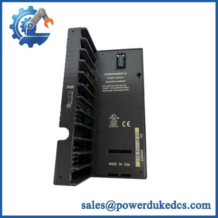
GE IC200ALG620
Module 3: Commercial-Technical Deep Dive
A failed temperature-input module can remove several RTD measurements from a VersaMax system without affecting the PLC CPU or unrelated I/O. The GE IC200ALG620 is a dedicated four-channel RTD input module that accepts direct resistance-temperature sensors rather than conventional 4–20 mA transmitters. Each channel supports 3-wire or 4-wire RTD connections, while the module supplies the required sensor excitation current. Supported sensor families include multiple platinum, copper, nickel, and nickel/iron RTD types, giving the same module considerable range across industrial temperature applications.
The conversion behavior matters when replacing a temperature card. GE specifies approximately 210 ms per channel at 60 Hz and 230 ms per channel at 50 Hz, while the documented RTD temperature accuracy is approximately ±0.15% at 25°C. The module provides 16-bit data with a documented 15-bit-plus-sign resolution description, and its configuration includes line frequency, RTD type, wire arrangement, channel activation, alarm limits, and nominal resistance. One useful field limitation: IC200ALG620 does not use loop power like a 4–20 mA input module; excitation is generated by the RTD module itself. That makes correct sensor type and wiring configuration critical during commissioning.
Module 4: Compatibility & Installation Traps
Migration/Compatibility
- System: GE VersaMax Modular I/O
- Full Model: IC200ALG620
- Module Type: 16-bit RTD analog input
- Channels: 4
- Sensor Wiring: 3-wire or 4-wire RTD
- Signal Basis: Resistance measurement converted to temperature or resistance data
- Resolution: 15 bits plus sign / 16-bit data representation
- Supported RTD Families: Platinum, copper, nickel, nickel/iron, plus supported resistance ranges
- Update Rate: Approx. 210 ms/channel at 60 Hz; 230 ms/channel at 50 Hz
- Configuration: Software-configured through supported VersaMax PLC/NIU environments
- Carrier Requirement: Compatible VersaMax carrier/terminal arrangement required
- Replacement Type: Exact IC200ALG620 revision match preferred
- Logic Rewrite: Normally not required for a like-for-like module replacement, but channel configuration and scaling must be verified
- Temperature Units: °C, °F, or resistance values depending on configuration
⚠️ Field Traps (Watch Out)
1. Do not wire it like a current-input module.
IC200ALG620 measures RTD resistance directly. The module supplies sensor excitation; it does not expect a 4–20 mA transmitter loop. Incorrect conversion to a current-loop architecture can produce completely invalid measurements.
2. Preserve the RTD type and wire configuration.
The module supports multiple RTD curves, including different platinum, copper, nickel, and nickel/iron types. The controller configuration must match the actual sensor. A 100-ohm platinum RTD configured as a different curve can produce a plausible-looking temperature while remaining materially wrong.
3. Verify 3-wire versus 4-wire termination.
The module supports both configurations, but the terminal wiring is different. A replacement card can pass its own self-test while every field temperature remains incorrect if the lead arrangement was copied incorrectly.
4. Check the line-frequency setting.
GE permits 50 Hz or 60 Hz configuration. The selected line frequency affects measurement behavior and filtering, so preserve the original setting when replacing the module.
5. Check alarm limits and inactive channels.
Each channel can be configured independently, including active/inactive state and high/low alarm limits. Replacing the hardware without restoring those parameters can create unexpected process alarms.
Module 5: Quality Assurance SOP
Each available GE IC200ALG620 should undergo a documented RTD-module inspection and functional test before shipment:
- OEM anti-counterfeit visual inspection: Verify GE/VersaMax identification, complete IC200ALG620 catalog number, front-panel labeling, LED arrangement, terminal markings, and manufacturing information.
- Revision verification: Record all visible hardware and firmware revision information before testing.
- Mechanical inspection: Check the module housing, carrier interface, terminal connections, locking features, and front-panel surfaces for damage.
- PCB condition inspection: Inspect accessible electronics for corrosion, contamination, cracked components, thermal discoloration, damaged traces, and evidence of previous repair.
- Power precheck: Perform controlled resistance and continuity checks before installation on the VersaMax carrier.
- Power-on self-test (POST): Install the module on an approved VersaMax test carrier and verify the OK LED behavior.
- Configuration handshake: Verify that the PLC or supported NIU recognizes the IC200ALG620 and accepts its configuration.
- RTD excitation test: Verify controlled excitation current on representative channels using an approved laboratory instrument.
- Channel-by-channel measurement test: Test all four inputs independently.
- RTD simulation: Use a precision RTD simulator or calibrated resistance source to emulate representative sensor values.
- Sensor-type verification: Test representative platinum, copper, or nickel configurations that correspond to the intended customer application.
- 3-wire test: Verify representative 3-wire RTD operation and lead-resistance compensation.
- 4-wire test: Verify representative 4-wire RTD operation.
- Temperature conversion test: Apply low, mid-scale, and high-scale resistance values and confirm the resulting digital temperature data.
- Line-frequency test: Verify representative 50 Hz and 60 Hz configuration behavior where the test fixture supports it.
- Open-wire test: Introduce controlled sensor disconnection and verify the expected diagnostic response.
- Short/input-fault test: Apply an approved simulated input fault and confirm the module reports the expected condition.
- Alarm test: Configure representative high and low limits and verify alarm reporting.
- Data-update test: Confirm the expected per-channel update behavior in the selected line-frequency configuration.
- Final QC record: Record catalog number, revision, RTD types tested, wiring modes, calibration points, line-frequency setting, alarm results, and technician sign-off.
- ESD-safe packaging: Package the module in ESD-protective material with mechanical protection around the carrier interface and terminal area.
For an RTD module, the strongest outgoing evidence is calibrated resistance injection across all four channels. A simple resistance check confirms the input circuit is present; it does not prove the correct RTD curve, lead compensation, diagnostics, or temperature conversion.
Module 6: CRO-Driven Buyer FAQ
What is GE IC200ALG620?
GE IC200ALG620 is a VersaMax 16-bit RTD analog input module with four channels. It accepts RTD sensors through 3-wire or 4-wire connections and supplies the sensor excitation from the module itself.
How many RTD channels does IC200ALG620 have?
It has four independent RTD input channels. Each channel can be configured for the supported sensor type and 3-wire or 4-wire connection.
What RTD types are supported?
The documented configurations include several platinum, copper, nickel, and nickel/iron sensor types, along with configurable resistance ranges. The exact sensor curve must be selected in the VersaMax configuration.
Does IC200ALG620 accept 4–20 mA signals?
No. This is an RTD/resistance input module, not a conventional current-input module. It measures resistance directly and supplies excitation to the connected RTD sensor.
What is the update rate?
GE documents approximately 210 ms per channel at 60 Hz and 230 ms per channel at 50 Hz. The module can be configured for either line frequency.
Can IC200ALG620 be replaced while the VersaMax system is powered?
GE documentation warns that improper hot insertion can disrupt other modules on the same backplane. Use the approved VersaMax installation procedure rather than treating the RTD module as automatically hot-swappable.
What should I verify before ordering IC200ALG620?
Confirm the exact IC200ALG620 part number and hardware revision, VersaMax carrier type, four-channel RTD requirement, actual sensor type, 3-wire or 4-wire wiring, 50/60 Hz setting, engineering units, alarm limits, and existing PLC/NIU configuration.
What warranty and technical support should I expect?
Warranty duration should be stated for the exact unit condition and test status on the quotation. Technical support should cover part-number verification, RTD compatibility, carrier matching, 3-wire/4-wire wiring review, configuration checks, and documented four-channel resistance/temperature testing. Process calibration and PLC application changes should be treated separately unless explicitly included.











 Start Chat


