

Description
- Brand: GE Fanuc
- Full Model Number: IC200CHS022E
- System / Series Family: VersaMax
- Core Function: Compact I/O carrier providing module mounting, backplane connections, and field wiring
- Top 3 Hardcore Specs: 36 IEC box-style terminals / 1 compatible I/O module / Up to 32 I/O points
- Mounting: 7.5 mm × 35 mm DIN rail
- Wiring: Single- or double-wire terminal connections
- Wire Type: Solid or stranded copper
- Dimensions: Approximately 163.5 × 70 × 66.8 mm
- Revision: E
- Stock Status: New Surplus / Factory Sealed — exact physical condition to be confirmed before quotation
Module 3: Technical Product Introduction
A failed carrier base can stop an otherwise healthy VersaMax I/O station from communicating with or physically connecting to its installed I/O module. The GE Fanuc IC200CHS022E is a Compact I/O Carrier for the VersaMax family. It provides the mounting interface, backplane communication path, and field-wiring connections for one compatible I/O module, supporting up to 32 I/O points and four common power connections. The carrier has 36 IEC box-style terminals and mounts on a 7.5 mm × 35 mm DIN rail.
The E suffix identifies a specific revision of the IC200CHS022 carrier family, so it should be preserved in procurement records when the installed cabinet calls for that revision. The published dimensions for the carrier are approximately 163.5 × 70 × 66.8 mm, with the product documentation also specifying provisions for single- or double-wire connections. For vibration-sensitive installations, the carrier can additionally be panel-mounted rather than relying solely on DIN-rail retention.
Module 4: Application Scenarios & Field Realities
- Inside a VersaMax I/O station, the IC200CHS022E provides the physical and electrical base for one compatible I/O module. If the carrier is damaged, replacing the I/O module alone will not restore the station’s field connections.
- For DIN-rail control cabinets, the carrier snaps onto a 7.5 mm × 35 mm rail. The DIN rail should be electrically grounded for EMC protection, and the installation should use a conductive, corrosion-resistant rail surface rather than an insulated or heavily painted mounting surface.
- Where field wiring is already terminated, the 36-terminal arrangement allows the carrier to handle the associated I/O and common power connections. Check the actual terminal assignment against the wiring card before moving conductors; carrier terminals should not be assumed to have identical functions across every VersaMax I/O module.
- In cabinets exposed to mechanical vibration, DIN-rail mounting alone may not provide the desired mechanical restraint. The available installation guidance recommends panel mounting as an additional measure where maximum resistance to vibration and shock is required.
Module 5: Migration, Compatibility & Installation Traps
Replacement Matrix
| Replacement Case | Classification | Engineering Requirement |
|---|---|---|
| IC200CHS022E replacing the identical IC200CHS022E | Drop-in Replacement | Verify revision, I/O module compatibility, terminal wiring, and DIN-rail arrangement |
| IC200CHS022 carrier with a different revision | Software Compatible — Verify First | Check the installed VersaMax hardware configuration and revision requirements |
| Different VersaMax carrier type | Hardware Modification Required | Recheck module compatibility, terminal layout, mounting, and field wiring |
| Carrier from another GE control family | Hardware Modification Required | Do not substitute based on physical dimensions alone |
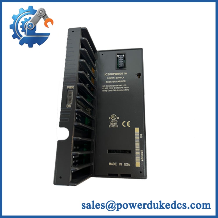
GE IC200CHS022E
Field Traps — Watch Out
Carrier-to-module compatibility: The IC200CHS022E is not itself an I/O signal module. It is the carrier that provides mounting, backplane connection, and field wiring for one compatible VersaMax I/O module. Make sure the replacement carrier and installed I/O module are an approved combination.
DIN-rail grounding: The installation guidance specifies an electrically grounded DIN rail for EMC protection. A painted rail with poor electrical continuity can undermine that requirement. Verify the rail’s grounding path before commissioning the station.
Airflow clearance: Published installation information recommends approximately 1 inch of horizontal and 2 inches of vertical spacing around the carrier for ventilation. Do not pack adjacent cabinet hardware tightly around the carrier simply because the physical unit fits.
Terminal handling: The carrier supports both single- and double-wire configurations, but the allowable conductor cross-sections differ. The published data specifies approximately 0.36–2.1 mm² for a single wire and up to approximately 0.86 mm² for double-wire connections. Confirm the applicable wiring specification before re-terminating field conductors.
Module 6: Quality Assurance SOP
The pre-shipment inspection for a GE Fanuc IC200CHS022E should focus on carrier revision, terminal integrity, mechanical condition, and backplane interfaces:
- Part-number verification — Confirm the physical identification as IC200CHS022E and record the complete revision marking.
- OEM anti-counterfeit visual inspection — Examine GE/GE Fanuc markings, labels, molded housing details, terminal markings, connector construction, and manufacturing identifiers for inconsistent printing or unauthorized alteration.
- Mechanical inspection — Check the carrier body, DIN-rail latch, mounting features, terminal block, card holder, connector interfaces, and keying features for cracks, deformation, broken latches, or impact damage.
- Terminal inspection — Inspect all 36 IEC box-style terminals for damaged clamping mechanisms, stripped hardware, contamination, corrosion, or loose components.
- Backplane interface inspection — Examine the male/female backplane connection for bent, contaminated, damaged, or displaced contacts. The connector should engage correctly without excessive force.
- Module-keying verification — Inspect the keying arrangement and confirm that the carrier’s configuration is suitable for the intended VersaMax I/O module.
- Continuity verification — Where an approved test fixture is available, verify applicable carrier terminal and backplane continuity against the correct wiring documentation.
- System handshake verification — Because the carrier itself is a passive mounting and connection component rather than a programmable CPU, system-level communication testing should be performed with a compatible VersaMax I/O module installed. Confirm that the complete I/O station recognizes and communicates with the module as expected.
- Final inspection and packaging — Photograph the exact IC200CHS022E identification, record inspection results, protect the backplane connector and terminals from contamination, and package the carrier against mechanical shock.
The acceptance record should tie the IC200CHS022E revision, terminal condition, mechanical inspection, backplane-interface check, and final packing record to the exact unit shipped. This is a carrier-base component, so connector integrity and terminal condition deserve as much attention as the part number itself.











 Start Chat


