

Description
- Brand: GE / GE Intelligent Platforms
- Full Model Number: IC200PWR012D
- System/Series Family: VersaMax PLC / Distributed I/O
- One-Sentence Core Function: Isolated power-supply module converting 24 VDC input into regulated 5 VDC and 3.3 VDC power for VersaMax CPU, network interface, and I/O modules
- Top 3 Hardcore Specs: 18–30 VDC input; 1.5 A maximum total output; 0.25 A maximum 3.3 VDC output
- Stock Status: New Surplus / Fully Tested Refurbished — exact PWR012D revision and electrical configuration verified before shipment
Module 3: Commercial-Technical Deep Dive
A VersaMax station can appear electrically dead even when the CPU, NIU, and I/O modules are healthy if the common logic supply has failed. The GE IC200PWR012D is the isolated 24 VDC power-supply module for the VersaMax architecture. GE’s VersaMax documentation identifies the IC200PWR012 family as a power supply that snaps onto a VersaMax CPU or Network Interface Unit, or onto a power-supply booster carrier. The isolated version provides regulated 5 VDC and 3.3 VDC rails for the station electronics, making it a rack-level power component rather than a field signal module.
The electrical limits are straightforward but easy to misapply. GE specifies an 18–30 VDC input range with 24 VDC nominal, 11 W input power, 10 ms holdup time, and an inrush current of up to 20 A at 24 VDC for 6 ms and 25 A at 30 VDC for 6 ms. Total output current is limited to 1.5 A; the standard 3.3 V output of the PWR012 configuration is limited to 0.25 A, with the remaining current available on the 5 V rail. The module also provides short-circuit, overload, and reverse-polarity protection.
Module 4: Compatibility & Installation Traps
Migration/Compatibility
- Replacement status: Configuration-specific VersaMax isolated power-supply module.
- Official family: IC200PWR012 — 24 VDC isolated power supply with 5 VDC and 3.3 VDC outputs.
- Input: 18–30 VDC, 24 VDC nominal.
- Output: 5 VDC + 3.3 VDC, 1.5 A maximum total. The 3.3 V output is limited to 0.25 A on the standard PWR012 configuration.
- Isolation: The PWR012 is the isolated version, unlike the non-isolated IC200PWR001/002 family members.
- Firmware requirement: None for the power-supply module itself.
- Logic rewrite: Not applicable. After replacement, verify that the CPU, NIU, and attached I/O modules initialize normally.
- Mounting compatibility: VersaMax power supplies snap onto compatible CPUs, network interface units, or a power-supply booster carrier.
⚠️ Field Traps (Watch Out)
- PWR012 versus PWR002: Both are 24 VDC supplies, but PWR012 is isolated, while PWR002 is not. Do not substitute based only on voltage and current ratings.
- 3.3 V current limit: The standard PWR012 configuration provides only 0.25 A maximum at 3.3 V. If the station requires more 3.3 V current, the and expanded-3.3-V configuration must be distinguished carefully.
- Input inrush: The external 24 VDC source should be sized for the specified peak inrush. A supply that is adequate at steady state can still trip during startup.
- Booster-carrier architecture: In larger VersaMax stations, a power-supply booster carrier can distribute additional power to modules further down the station. Verify where the PWR012D is physically installed before assuming which modules it feeds.
- Reverse-polarity risk: Although the module includes reverse-polarity protection, correct field polarity should still be verified before energization.
- ESD and power isolation: Remove the 24 VDC source before extraction and use grounded ESD handling for the module and its connector.
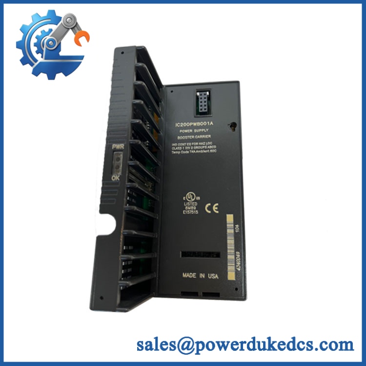
GE IC200PWR012D
Module 5: Quality Assurance SOP
Our pre-shipment inspection for a GE IC200PWR012D focuses on isolation, output-rail stability, startup behavior, and exact hardware identification:
- OEM anti-counterfeit visual inspection — verify GE identification, complete IC200PWR012D marking, revision information, serial/label data, connector condition, and PCB construction.
- Part-number capture — photograph the front, rear, label area, connector, and all secondary identification markings.
- Revision verification — compare the supplied D revision against the customer’s removed module where photographs or label data are available.
- Mechanical inspection — inspect the housing, snap-fit interface, terminal area, connector, ventilation openings, and signs of impact or overheating.
- Input-stage inspection — check visible protection components and input terminals for corrosion, cracked solder joints, contamination, or thermal damage.
- Controlled 24 VDC power test — apply an isolated laboratory supply within the specified 18–30 VDC range and monitor startup current.
- Power-on self-test (POST) — confirm stable startup behavior and absence of abnormal current draw or heating.
- 5 VDC output verification — measure the regulated 5 V rail at no load and under representative load.
- 3.3 VDC output verification — measure the 3.3 V rail and confirm operation within the applicable 0.25 A output limit for the standard configuration.
- Total-load test — apply a controlled combined load while keeping total output current at or below 1.5 A.
- Isolation verification — where the approved test fixture permits, verify the expected isolation characteristics between the input and logic/output domains.
- Protection screening — perform controlled short-circuit, overload, and reverse-polarity protection checks only within the manufacturer’s permitted test limits.
- Holdup observation — verify the power supply maintains output during the specified transient interruption condition where the test facility supports this check.
- VersaMax station test — install the module on a compatible CPU, NIU, or booster-carrier test assembly and confirm normal initialization of connected modules.
- Extended-load observation — monitor 5 V and 3.3 V stability, temperature rise, and current draw during representative continuous operation.
- Configuration record — document part number, revision, input voltage, 5 V reading, 3.3 V reading, load current, isolation-test result, and photographs.
- Final ESD packaging — protect the connector and module body against ESD, impact, dust, and moisture before shipment.
GE documentation identifies the family as an isolated 24 VDC power supply, with 5 VDC and 3.3 VDC outputs, 1.5 A total output capacity, and 0.25 A maximum 3.3 V output for the standard configuration.
Module 6: CRO-Driven Buyer FAQ
1. Is GE IC200PWR012D obsolete?
The IC200PWR012D is part of the established GE VersaMax power-supply family and remains available through installed-base supply channels. The current GE-era technical catalog referenced here lists the IC200PWR012 family as an active VersaMax power-supply type, although the exact D-revision lifecycle should be confirmed against the physical unit and current GE/Emerson records.
2. What is the input voltage for ?
The documented input range is 18–30 VDC, with 24 VDC nominal. Input power is specified at 11 W.
3. What outputs does the provide?
The module provides 5 VDC and 3.3 VDC regulated output rails. Total output current is 1.5 A maximum, while the standard configuration limits the 3.3 V output to 0.25 A maximum.
4. Is isolated?
Yes. GE classifies the IC200PWR012 as a 24 VDC isolated power supply, distinguishing it from non-isolated VersaMax PWR001/PWR002 units.
5. Can be hot-swapped?
Do not assume live replacement is permitted. The module supplies the VersaMax station’s internal logic rails and may be mounted directly on a CPU, NIU, or booster carrier. Remove the external 24 VDC supply and follow the applicable VersaMax maintenance procedure before extraction.
6. What warranty and technical support should I expect?
Warranty duration should be stated on the quotation for the exact physical module supplied. Technical support should cover part-number and revision verification, isolated/non-isolated variant matching, 24 VDC input checks, 5 V and 3.3 V rail testing, load verification, and documented pre-shipment QA results. It should not substitute for PLC system engineering, cabinet power-budget analysis, or site commissioning.











 Start Chat


