

Description
- Brand: GE Fanuc
- Full Model Number: IC660EBD020
- System/Series Family: Genius I/O
- One-Sentence Core Function: Electronics assembly for the IC660BBD020 24/48 VDC 16-circuit source I/O block
- Top 3 Hardcore Specs: 24/48 VDC source I/O architecture; 16 configurable circuits; 2 A steady-state output per circuit
- Stock Status: New Surplus / Fully Tested Refurbished — exact electronics assembly and hardware revision verified before shipment
Module 3: Commercial-Technical Deep Dive
The electronics inside a Genius I/O block can fail while the existing terminal base and field wiring remain perfectly serviceable. The GE IC660EBD020 is the electronics assembly used with the IC660TSD020 terminal base to form the IC660BBD020 24/48 VDC 16-circuit source I/O block. GE’s original Genius I/O manual explicitly maps IC660EBD020 to the IC660BBD020 family and identifies the same electronics assembly in the related 24 VDC source-block configuration. Each circuit can be configured as an input, tristate input, or output, with output feedback available when the block operates as a combination I/O device.
The electrical limits make this more than a simple board swap. The documented 24/48 VDC block accepts 18–56 VDC, while the dedicated 24 VDC version uses 18–30 VDC; output capability is 2 A per circuit, with up to 10 A inrush for 10 ms and a 15 A block-current limit at 35°C. Input processing is typically 1.7 ms plus selectable filter delay, with selectable filtering from 5–100 ms. GE also specifies diagnostics for open wire, overtemperature, failed switch, short circuit, overload, and no-load conditions. These characteristics must be matched to the exact terminal assembly and field-voltage configuration rather than inferred from the IC660EBD020 name alone.
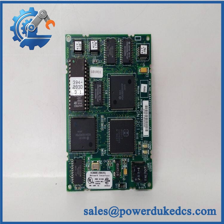
GE IC660EBD020
Module 4: Compatibility & Installation Traps
Migration/Compatibility
- Replacement status: Configuration-specific Genius I/O electronics assembly.
- Official relationship: IC660EBD020 is the electronics assembly used with IC660TSD020 to form the IC660BBD020 24/48 VDC 16-circuit source I/O block.
- Functional identity: Electronics assembly, not the complete terminal-base block.
- System family: GE Genius I/O distributed control architecture.
- Firmware requirement: No separate firmware procedure should be assumed for a like-for-like electronics replacement; preserve Genius Bus configuration and block parameters.
- Logic rewrite: Normally not required, but point configuration, Genius Bus address, input/output assignments, filtering, and diagnostics must be verified.
- Terminal-base requirement: Confirm the installed IC660TSD020 terminal assembly before approving replacement.
⚠️ Field Traps (Watch Out)
- Wrong terminal assembly: IC660EBD020 is paired with IC660TSD020 for the 24/48 VDC source configuration. Installing an electronics assembly against the wrong terminal base can create an electrical mismatch.
- Voltage-range confusion: The 24/48 VDC block and dedicated 24 VDC block use different operating ranges. Verify the actual field supply before energizing.
- Source-versus-sink architecture: belongs to the source I/O family. Do not substitute the related IC660EBD021 sink electronics without checking the complete block design.
- Circuit configuration: The 16 circuits may be configured as inputs, tristate inputs, or outputs. Preserve the existing channel assignment rather than assuming every channel has the same role.
- Output loading: The 2 A per-circuit rating does not eliminate inrush considerations. Solenoids, contactors, and other inductive loads should be checked against their startup current.
- Genius Bus addressing: Preserve the original block address and configuration. A healthy electronics assembly can still appear offline if the network identity is wrong.
- ESD and electrical isolation: Remove field/control power and use grounded ESD handling before replacing the electronics assembly.
Module 5: Quality Assurance SOP
Our pre-shipment inspection for a focuses on electronics integrity, circuit switching, diagnostic behavior, and terminal-base compatibility:
- OEM anti-counterfeit visual inspection — verify GE Fanuc/Genius identification, complete number, revision markings, PCB artwork, component population, connectors, and manufacturing labels.
- Assembly relationship verification — confirm the intended mating terminal assembly is IC660TSD020 for the 24/48 VDC source-block configuration.
- Part-number capture — photograph all labels, connector areas, PCB markings, and secondary identification data.
- PCB inspection — check solder joints, smart-switch components, RC snubbers, LEDs, connectors, contamination, corrosion, and thermal discoloration.
- 24/48 VDC supply verification — where testing the 24/48 VDC configuration, apply a controlled input within the documented 18–56 VDC range.
- Power-on self-test (POST) — verify startup behavior, module status indication, and abnormal current draw.
- Sixteen-channel input test — stimulate representative input channels and confirm correct state acquisition.
- Output-channel test — command representative outputs through a controlled load and verify switching behavior.
- Current-load verification — test representative outputs while staying below the documented 2 A per circuit continuous rating and observe the block-level current limit.
- Inrush-response test — where appropriate, use a controlled inductive load to evaluate switching behavior against the specified 10 A / 10 ms inrush limit.
- Input-filter test — verify representative configured filter behavior against the applicable 5–100 ms setting.
- Diagnostic verification — test available open-wire, overtemperature, failed-switch, short-circuit, overload, and no-load diagnostics using a controlled fixture.
- Genius Bus communication handshake verification — connect the electronics assembly through its compatible terminal base and verify communication with a Genius Bus controller.
- Address verification — confirm the block’s configured network address and representative data exchange.
- Extended operation test — monitor I/O stability, diagnostic status, temperature, and intermittent switching behavior during controlled continuous operation.
- Configuration record — document part number, hardware revision, terminal-base type, supply voltage, circuit mapping, load-test results, diagnostics, and photographs.
- Final QC review — cross-check every identifier against the customer’s exact requirement.
- ESD packaging — protect the PCB and mating interfaces from ESD, moisture, dust, and mechanical impact before shipment.
GE’s original manual is especially useful for this part because it directly establishes the relationship among IC660BBD020, IC660TSD020, and , as well as the source/sink block architecture and electrical performance limits.
Module 6: CRO-Driven Buyer FAQ
1. Is GE the complete I/O block?
No. is the electronics assembly. For the 24/48 VDC source configuration, it mates with to form the complete IC660BBD020 block.
2. What complete block uses ?
GE’s Genius I/O manual identifies as the 24/48 VDC 16-circuit source I/O block using as the terminal assembly and as the electronics assembly. The same electronics assembly is also listed for the related IC660BBD022 24 VDC source block.
3. What voltage does support?
The electronics assembly is used in a 24/48 VDC source-I/O configuration, for which GE documents an 18–56 VDC operating range. The related dedicated 24 VDC block uses 18–30 VDC. Confirm the terminal assembly and complete block configuration before applying field power.
4. How many I/O circuits does provide?
It supports 16 discrete circuits. Each circuit can be configured as an input, tristate input, or output, subject to the complete block configuration and field-wiring architecture.
5. What output current can the block handle?
The documented steady-state output rating is 2 A per circuit, with 10 A maximum inrush for up to 10 ms and a 15 A block output-current limit at 35°C. Actual loads should be checked for inrush and thermal conditions.
6. Can be hot-swapped?
Do not assume live replacement is permitted. The electronics assembly interfaces with external field power and Genius Bus wiring. Remove the applicable power sources, verify the circuit is safe, and follow the GE Genius I/O maintenance procedure and site LOTO requirements before replacement.
7. What warranty and technical support should I expect?
Warranty duration should be stated on the quotation for the exact electronics assembly supplied. Technical support should cover identification, terminal-base matching, source/sink verification, Genius Bus addressing, I/O configuration, circuit testing, and documented pre-shipment QA results. It should not substitute for PLC engineering, field-wiring validation, or site commissioning.











 Start Chat


