

Description
- Brand: GE / GE Fanuc
- Full Model Number: IC660EBD025
- System/Series Family: GE Genius I/O
- Core Function: Electronics assembly for the IC660BBD025 32-circuit discrete sink I/O block
- Block Family: BBD025
- Circuit Count: 32 discrete circuits
- Signal Type: 5 / 12 / 24 VDC TTL-compatible sink I/O
- Power Supply: 5 VDC for sink-block operation; 12/24 VDC system configurations also documented
- Operating Voltage: 10–30 VDC from single source; 4.9–5.3 VDC for 5 V sink operation
- Block-to-Block Isolation: 850 V
- Maximum Output Current: 0.5 A per circuit
- Maximum Total Output Current: 16 A
- Power Supply Current: 300 mA maximum; 150 mA typical
- Physical Size: Approx. 8.83 × 3.56 × 4.42 in
- Weight: Approx. 4 lb / 1.8 kg
- Stock Status: New Surplus / Fully Tested Refurbished — verify exact revision and BBD025 terminal assembly compatibility
GE Genius documentation identifies IC660EBD025 as the Electronics Assembly for IC660BBD025, a 32-circuit 5/12/24 VDC TTL sink I/O block. GE’s documentation specifies 850 V block-to-block isolation, approximately 1.8 kg weight, and a 0.5 A maximum steady-state output current per circuit.
Module 3: Commercial-Technical Deep Dive
When a legacy Genius I/O block develops internal electronic faults, replacing the complete field terminal assembly may be unnecessary. The GE IC660EBD025 is the electronic assembly associated with the IC660BBD025 32-circuit sink I/O block. GE classifies the BBD025 architecture as a 32-circuit, 5/12/24 VDC TTL-compatible sink block, allowing the electronic assembly to process a large number of discrete field signals while retaining the existing terminal assembly. That distinction matters during maintenance: EBD025 is the electronics assembly, not the complete BBD025 block.
The hard ROI comes from preserving the installed Genius field wiring and terminal hardware when the electronic section is the failed component. GE specifies 0.5 A maximum steady-state output current per circuit, with a documented 16 A total block output current limit, plus 850 V block-to-block isolation. The architecture also supports input devices such as two-wire and three-wire solid-state sensors. —Do not confuse the 0.5 A circuit rating with a 16 A rating on every channel; thermal and total-current limits remain system-level constraints.
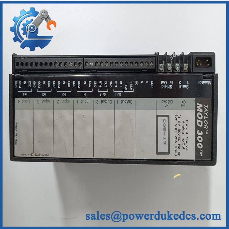
GE IC660EBD025
Module 4: Compatibility & Installation Traps
Migration/Compatibility
For an existing GE Genius I/O installation specified for IC660EBD025, the appropriate replacement strategy is an exact electronics-assembly replacement, provided the installed block is the corresponding IC660BBD025 and the revision is compatible.
No PLC logic rewrite is normally required because the electronics assembly preserves the existing Genius I/O block architecture. The key checks are the BBD025 block type, terminal assembly, revision, supply configuration, Genius bus configuration, and field-device wiring.
GE documentation treats the complete I/O block as separate assemblies: IC660BBD025 is the complete block, IC660TBD025 is the terminal assembly, and IC660EBD025 is the electronics assembly. That separation is critical when ordering a spare.
⚠️ Field Traps (Watch Out)
- EBD025 versus BBD025: Do not quote IC660EBD025 as though it were the complete field I/O block. The electronics assembly is intended for IC660BBD025, while IC660TBD025 is the corresponding terminal assembly.
- Revision compatibility: The final suffix after the base number identifies the electronics revision. Later revisions may use a newer electronic housing and can require the corresponding plastic door or have terminal-strip compatibility considerations. Verify the revision on the installed assembly before substitution.
- 5 V versus 12/24 V configuration: The is unusual because the sink architecture supports 5, 12, and 24 VDC configurations, with the 5 V version using a 4.9–5.3 VDC supply range. Verify the installed block’s actual power architecture before energization.
- Terminal assembly reuse: If replacing only the electronic assembly, inspect the mating terminal assembly and connector carefully. A damaged terminal strip can produce the same field symptoms as a failed electronics card.
- Genius bus configuration: The replacement electronics must retain the existing Genius network identity and configuration. A healthy board with the wrong bus address can remain invisible to the controller.
Module 5: Quality Assurance SOP
- OEM anti-counterfeit visual inspection — verify GE/GE Fanuc identification, complete marking, PCB layout, connector arrangement, revision marking, and evidence of unauthorized modification.
- Part-number reconciliation — photograph the electronics assembly number, revision, serial information, and every secondary identifier.
- compatibility check — confirm the intended mating assembly is with the appropriate IC660TBD025 terminal hardware.
- Mechanical inspection — inspect the electronic housing, board connector, terminal interface, mounting points, door compatibility, and PCB for cracks, corrosion, contamination, or rework.
- Power-on self-test (POST) — install the electronics assembly into an approved test block and apply the correct supply configuration.
- Genius Bus handshake verification — connect the test block to a representative Genius network and verify node recognition and communication.
- Discrete input verification — stimulate representative input channels using the appropriate 5/12/24 V test levels and confirm correct state recognition.
- Discrete output verification — command representative output channels into controlled loads and verify correct switching behavior.
- Current-load verification — test representative outputs within the documented 0.5 A per-circuit limit and verify stable operation.
- Isolation verification — where the approved test fixture permits, verify the applicable block-to-block isolation requirement associated with the 850 V specification.
- Diagnostic verification — verify the block’s Unit OK, I/O Enabled, and individual circuit indications under normal and controlled fault conditions.
- Thermal stability observation — operate multiple channels under representative load while monitoring temperature, output stability, and intermittent behavior.
- Final QC release — retain identification photographs, revision information, Genius address/configuration records, I/O test results, and packaging inspection documentation.
For an electronic assembly intended to restore a legacy Genius block, the meaningful QA result is correct operation inside the terminal assembly, not a bench power-up of the PCB alone.
Module 6: CRO-Driven Buyer FAQ
1. What is GE ?
It is the electronics assembly for the GE Genius 32-circuit sink I/O block. GE documentation identifies the complete as a 32-circuit 5/12/24 VDC TTL sink block, with serving as its electronics assembly.
2. Is a complete Genius I/O block?
No. The Genius block is assembled from separate components: is the complete I/O block, IC660TBD025 is the terminal assembly, and is the electronics assembly.
3. What is the output current rating?
The documented steady-state output current is 0.5 A maximum per circuit, with a 16 A total block output-current limit. The complete load must also remain within the applicable thermal limits of the block and cabinet.
4. What voltage does the architecture use?
GE documentation identifies the as a 5/12/24 VDC sink block. For 12/24 V configurations, the single-source operating range is 10–30 VDC; for the 5 V sink configuration, the supply range is 4.9–5.3 VDC.
5. Is interchangeable with IC660EBD024?
No. EBD025 belongs to the sink-block architecture, while EBD024 corresponds to the BBD024 source-block architecture. Verify source/sink topology and the complete terminal assembly before substitution.
6. Can be hot-swapped?
Do not assume hot-swap capability. The electronics assembly connects to active field I/O, block power, and the Genius communications system. Follow the GE Genius I/O maintenance and electrical-isolation procedure before removing or installing the assembly.
7. What warranty and technical support should I expect?
The quotation should clearly state whether the electronics assembly is new surplus, unused, or tested refurbished and specify the warranty period. Technical support should cover exact revision identification, /TBD025 compatibility, Genius address configuration, discrete I/O testing, and documented QC results. PLC application changes, field-wiring modifications, and site commissioning should remain separate engineering activities.











 Start Chat


