

Description
- Brand: GE Fanuc
- Full Model Number: IC660ELB912
- System/Series Family: Genius I/O / PC Interface Module
- One-Sentence Core Function: MicroGENI daughterboard providing the Genius I/O network interface inside GE PCIM assemblies
- Top 3 Hardcore Specs: 5 VDC ±10%; 400 mA maximum; 16 KB host-memory requirement
- Board Type: MicroGENI Network Interface Daughterboard
- Compatible Single-Channel PCIM: IC660ELB921
- Compatible Dual-Channel PCIM: IC660ELB922
- Communication Protocol: Genius I/O
- Supported Baud Rates: 38.4 kbit/s; 76.8 kbit/s; 153.6 kbit/s standard; 153.6 kbit/s extended
- Maximum Bus Devices: 30
- LEDs: GENI OK; COMMS OK
- Host Interface: ISA-compatible PCIM architecture
- Operating Temperature: 0°C to +60°C
- Humidity: 5% to 95% non-condensing
- Stock Status: New Surplus / Fully Tested Refurbished subject to availability
GE’s PCIM documentation identifies IC660ELB912 as the MicroGENI daughterboard, used with the single-channel IC660ELB921 or dual-channel IC660ELB922 PCIM. GE specifies a 5 VDC ±10% supply with 400 mA maximum consumption and 16 KB of host memory per daughterboard.
Module 3: Commercial-Technical Deep Dive
A failed MicroGENI board can interrupt an entire legacy PC-based Genius I/O interface even when the host computer and remote Genius blocks remain healthy. The GE IC660ELB912 is a PCIM daughterboard, not a standalone field I/O block. It provides the Genius network interface within the GE single-slot PCIM architecture and is installed on an IC660ELB921 single-channel PCIM or IC660ELB922 dual-channel PCIM. The board uses the Genius communications architecture to exchange data with remote I/O devices, with the documented network supporting up to 30 bus devices.
The electrical and memory requirements are modest but precise. GE specifies 5 VDC ±10% and 400 mA maximum for the daughterboard, while each installed daughterboard requires 16 KB of host memory. Supported Genius communication rates are 38.4 kbit/s, 76.8 kbit/s, 153.6 kbit/s standard, and 153.6 kbit/s extended. Two status indicators—GENI OK and COMMS OK—provide a useful first-level diagnostic distinction between board/network initialization and communications activity. Because the IC660ELB912 is a daughterboard, replacing it without verifying the host PCIM model, software environment, and existing Genius configuration can leave a healthy board unable to function correctly in the field.
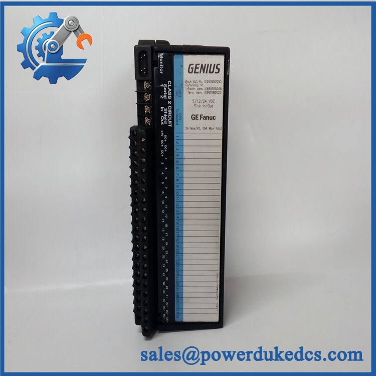
GE IC660ELB912
Module 4: Compatibility & Installation Traps
Migration/Compatibility
- System: GE Genius I/O
- Full Model: IC660ELB912
- Functional Designation: MicroGENI daughterboard
- Host Hardware: IC660ELB921 single-channel PCIM; IC660ELB922 dual-channel PCIM
- Network: Genius I/O bus
- Maximum Bus Devices: 30
- Communication Rates: 38.4, 76.8, 153.6 standard, 153.6 extended kbit/s
- Supply: 5 VDC ±10%
- Maximum Current: 400 mA
- Host Memory: 16 KB per daughterboard
- Diagnostics: GENI OK and COMMS OK LEDs
- Replacement Type: Exact IC660ELB912 replacement preferred
- Configuration: Preserve Genius bus address, baud rate, host software configuration, and PCIM channel assignment
- Logic Rewrite: Normally not applicable to the daughterboard itself; host software and Genius configuration must be validated
⚠️ Field Traps (Watch Out)
1. Do not purchase as though it were a complete PCIM.
The is the MicroGENI daughterboard. The complete PCIM assembly uses an IC660ELB921 or IC660ELB922 host board. A replacement daughterboard therefore has to match the existing PCIM architecture.
2. Do not confuse the single- and dual-channel PCIM arrangements.
IC660ELB921 supports one MicroGENI daughterboard, while IC660ELB922 supports two. In a dual-channel PCIM, the installed daughterboard position and channel assignment must be preserved.
3. Preserve the Genius baud-rate configuration.
The supported rates include 38.4, 76.8, 153.6 standard, and 153.6 extended kbit/s. All devices communicating on the applicable Genius network must use compatible network settings. A board can pass a power test while the network remains offline because of configuration mismatch.
4. Treat the two LEDs as diagnostic evidence.
The GENI OK and COMMS OK indications should be recorded during troubleshooting. A board with normal power but an abnormal COMMS indication requires network/configuration investigation before it is condemned.
5. Use ESD controls when handling the daughterboard.
GE documentation specifies static-sensitive handling for the board. The daughterboard should remain protected until installation, with grounded handling procedures used during removal and insertion.
Module 5: Quality Assurance SOP
Each available GE should undergo a documented MicroGENI inspection and functional test before shipment:
- OEM anti-counterfeit visual inspection: Verify GE Fanuc/Genius identification, complete catalog number, PCB markings, connector arrangement, component layout, and manufacturing identifiers.
- Host-architecture verification: Record whether the test assembly uses or and document the daughterboard channel position.
- PCB condition inspection: Check for corrosion, contamination, cracked components, damaged traces, thermal discoloration, loose components, and evidence of previous repair.
- Connector inspection: Examine board-edge contacts and mating interfaces for oxidation, contamination, bent contacts, and mechanical damage.
- ESD inspection: Handle only at a grounded ESD workstation and confirm no static-damage evidence is visible.
- Power precheck: Verify resistance and continuity before applying the specified 5 VDC supply.
- Power-on self-test (POST): Install the daughterboard on a compatible PCIM test fixture and verify startup behavior.
- Supply verification: Apply controlled 5 VDC within the ±10% specified range and measure current consumption under the approved test condition.
- GENI OK verification: Confirm the expected board/network initialization indication.
- COMMS OK verification: Establish a controlled Genius network and confirm the communications-status indication.
- Genius bus handshake verification: Connect representative Genius devices and verify correct network communication.
- Baud-rate testing: Test supported communication rates within the approved laboratory configuration.
- Bus-device test: Verify representative communication with multiple Genius I/O devices, up to the applicable test-fixture limit.
- Configuration verification: Confirm the tested Genius network address and baud-rate configuration against the customer’s approved baseline.
- Host-memory verification: Confirm that the host environment recognizes the daughterboard and allocates the required 16 KB memory.
- Fault simulation: Interrupt the controlled Genius network and verify the expected COMMS diagnostic response.
- Dual-channel test: Where the is installed on an , verify the correct daughterboard/channel assignment.
- Final QC record: Record catalog number, host PCIM model, channel position, supply voltage, current consumption, Genius baud rate, device count, LED results, and technician sign-off.
- ESD-safe packaging: Package the daughterboard in ESD-protective material with rigid protection around its connectors and PCB edges.
For this component, the strongest test result is successful communication through the actual PCIM host architecture. A loose-board power test does not prove that the MicroGENI interface, host memory allocation, Genius bus timing, and software environment operate correctly together.
Module 6: CRO-Driven Buyer FAQ
What is GE ?
GE is the MicroGENI daughterboard used in GE Genius I/O PC Interface Module assemblies. It provides the Genius network-interface function inside an or PCIM.
Which PCIM modules are compatible with ?
The documented host assemblies are , the single-channel PCIM, and , the dual-channel PCIM. The can accommodate two daughterboards.
What power does require?
GE specifies 5 VDC ±10% with a maximum consumption of 400 mA. Each daughterboard also requires 16 KB of host memory.
What Genius communication speeds are supported?
The documented rates are 38.4 kbit/s, 76.8 kbit/s, 153.6 kbit/s standard, and 153.6 kbit/s extended. The network architecture can support up to 30 bus devices through the PCIM arrangement.
Is a complete Genius controller?
No. It is a daughterboard. The complete PCIM hardware includes the or host board, and the host assembly provides the PC interface required by the application.
Is obsolete?
Yes. The belongs to GE Fanuc’s legacy Genius I/O PCIM architecture and is documented as an obsolete component in current industrial inventories. That makes exact host-board compatibility and revision identification important for replacement sourcing.
Can be replaced while the PCIM is powered?
Do not assume live replacement is permitted. It is a static-sensitive daughterboard installed inside a host PCIM assembly. Follow the applicable GE service procedure, remove power, and use grounded ESD handling before removing or installing the board. GE documentation specifically calls for static-sensitive handling of the µGENI board.
What should I verify before ordering ?
Confirm the exact identifier, host PCIM model (), daughterboard channel position, Genius bus address, baud rate, host software environment, and 5 VDC supply arrangement. A clear photograph of the existing PCIM assembly and daughterboard label is useful for exact matching.
What warranty and technical support should I expect?
Warranty duration should be stated for the exact unit condition and test status on the quotation. Technical support should cover part-number verification, PCIM compatibility, channel assignment, Genius-bus configuration, ESD handling, and documented communication testing. Legacy PC software integration, Genius network engineering, and production commissioning should be treated separately unless explicitly included.











 Start Chat


