

Description
- Brand: GE Fanuc
- Full Model Number: IC660TBD024
- System/Series Family: Genius I/O
- One-Sentence Core Function: Terminal assembly providing field wiring, power distribution, and connection between the IC660BBD024 I/O block and external discrete devices
- Top 3 Hardcore Specs: 32 circuits; 5/12/24 VDC sink architecture; 0.5 A per circuit
- Compatible I/O Block: IC660BBD024
- Compatible Electronics Assembly: IC660EBD024
- Circuit Count: 32
- Voltage Classes: 5, 12, 24 VDC
- I/O Architecture: Sink-type discrete I/O
- Output Current: 0.5 A per circuit steady state
- Aggregate Output Current: 16 A
- Input Filter: Selectable approximately 1–100 ms
- Block-to-Block Isolation: 850 VAC class
- Proximity-Switch Support: 2-wire and 3-wire devices
- Configuration Memory: Onboard EEPROM stores block configuration data
- Operating Temperature: 0°C to +60°C
- Stock Status: New Surplus / Fully Tested Refurbished subject to availability
GE’s Genius I/O documentation identifies IC660TBD024 as the terminal assembly for IC660BBD024, while the associated electronics assembly is IC660EBD024. GE’s catalog explicitly states that the complete block catalog number includes the terminal assembly and electronics assembly, which may also be ordered separately.
Module 3: Commercial-Technical Deep Dive
A damaged terminal assembly can take an otherwise healthy Genius I/O block out of service because field wiring, power distribution, and the electronics assembly all depend on the correct terminal architecture. The GE IC660TBD024 is specifically the terminal assembly used with the IC660BBD024 32-circuit 5/12/24 VDC sink I/O block. It serves as the field-wiring interface between the IC660EBD024 electronics assembly and external devices. GE documentation separates these components deliberately: IC660TBD024 is the terminal assembly, IC660EBD024 is the electronics assembly, and IC660BBD024 is the complete I/O block.
The field ratings explain why exact matching matters. Available technical records specify 32 circuits, 5/12/24 VDC operation, up to 0.5 A steady-state per output circuit, and an aggregate block output capability of 16 A. Selectable input filtering is available from approximately 1 to 100 ms, while the assembly supports both 2-wire and 3-wire proximity switches. An onboard EEPROM stores configuration information such as the device number, reference address, baud rate, and bus-related settings. This is therefore more than a passive terminal strip; it is part of the functional Genius block assembly.
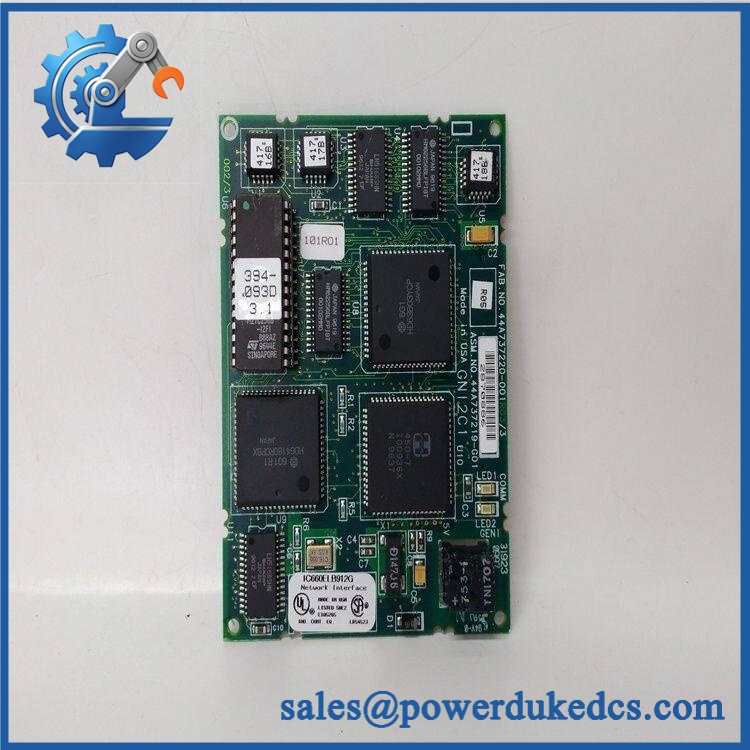
GE IC660TBD024
Module 4: Compatibility & Installation Traps
Migration/Compatibility
- System: GE Fanuc Genius I/O
- Full Model: IC660TBD024
- Assembly Type: Terminal Assembly
- Primary Compatible Block: IC660BBD024
- Compatible Electronics: IC660EBD024
- Circuit Count: 32
- Voltage Classes: 5, 12, 24 VDC
- I/O Type: Sink
- Output Capability: 0.5 A per circuit
- Aggregate Output Current: 16 A
- Proximity Devices: 2-wire and 3-wire
- Configuration Storage: EEPROM
- Replacement Type: Exact IC660TBD024 revision and mechanical version preferred
- Complete Block Relationship: = terminal assembly + IC660EBD024 electronics assembly
- Logic Rewrite: Normally not required for a terminal-assembly replacement, but field wiring and stored block configuration must be verified
⚠️ Field Traps (Watch Out)
1. Do not order as a complete I/O block.
GE documentation distinguishes the terminal assembly from the electronics assembly. The complete includes both. A replacement terminal assembly alone will not replace failed electronics.
2. Match the exact revision and housing style.
Field documentation lists variants from earlier revisions through later versions. A later revision can use a different electronic housing and may require the corresponding plastic door or terminal-strip arrangement. Verify the suffix on the installed assembly before shipment.
3. Preserve the EEPROM configuration.
Available service records associate the terminal assembly with EEPROM-stored configuration including device number, reference address, baud rate, and bus-related parameters. Record or preserve these settings before replacing the assembly.
4. Verify the field-voltage class.
The architecture covers 5, 12, and 24 VDC applications. Do not assume the same external wiring arrangement is correct for every voltage configuration.
5. Respect the total current limit.
A 0.5 A rating per circuit does not mean the entire assembly can deliver 16 A through every possible wiring arrangement without regard to the aggregate rating. The documented total output limit is 16 A.
Module 5: Quality Assurance SOP
Each available GE should undergo a documented terminal-assembly inspection and controlled functional test before shipment:
- OEM anti-counterfeit visual inspection: Verify GE Fanuc/Genius I/O identification, complete catalog number, terminal labels, housing markings, connector arrangement, and manufacturing identifiers.
- Revision verification: Record the complete visible revision suffix and compare the mechanical housing against the installed version.
- Compatibility verification: Confirm the intended electronics assembly is and the complete block architecture is .
- Mechanical inspection: Check terminal strips, mounting hardware, card/electronics interface, housing, cover, guides, and connector interfaces.
- Terminal inspection: Inspect every field terminal for oxidation, looseness, cracked insulation, damaged threads, and evidence of overheating.
- EEPROM inspection: Verify the configuration-memory interface and confirm that the stored configuration can be read or preserved where the test fixture supports it.
- Power-off continuity test: Verify representative terminal-to-interface paths before energization.
- Power-on self-test (POST): Assemble the terminal unit with a compatible electronics assembly and verify normal block startup.
- Genius bus handshake verification: Connect the complete assembly to an approved Genius test network and confirm recognition at the assigned device address.
- Input test: Exercise representative discrete input circuits using the applicable voltage class.
- Output test: Drive representative output circuits into controlled laboratory loads and verify correct switching.
- Load verification: Keep individual output current within the documented 0.5 A per-circuit limit and aggregate loading within the applicable 16 A limit.
- 2-wire proximity test: Verify representative 2-wire proximity-device wiring where applicable.
- 3-wire proximity test: Verify representative 3-wire proximity-device wiring where applicable.
- Input-filter test: Confirm representative selectable filter settings within the applicable configuration range.
- Diagnostic test: Introduce controlled open-wire or switching faults and verify expected block diagnostics.
- Configuration-memory test: Confirm device number, reference address, baud-rate, and related configuration information are retained correctly.
- Final QC record: Record catalog number, revision, compatible electronics assembly, terminal continuity, input/output results, configuration data, and technician sign-off.
- ESD-safe packaging: Protect the assembly against static discharge, impact, contamination, and terminal damage.
For this component, the most meaningful outgoing test is performed with the matching electronics assembly installed. Testing the terminal assembly in isolation cannot fully verify the field-to-Genius signal path.
Module 6: CRO-Driven Buyer FAQ
What is GE ?
GE is the terminal assembly for the Genius I/O block. It provides the field-wiring and power interface associated with the 32-circuit 5/12/24 VDC sink I/O architecture.
What electronics assembly works with ?
The documented compatible electronics assembly is . GE’s Genius documentation identifies the complete as the combination of terminal assembly and electronics assembly.
How many circuits does support?
It is the terminal assembly for a 32-circuit Genius sink I/O block. The associated architecture supports 5, 12, and 24 VDC discrete applications.
What is the maximum output current?
The documented steady-state output capability is 0.5 A per circuit, with an aggregate block output-current capability of 16 A. These limits should be respected during field design and laboratory testing.
Does store configuration data?
Available technical records identify an EEPROM that stores configuration information such as device number, reference address, baud rate, and bus-related parameters. Preserve this configuration when replacing the terminal assembly.
Is interchangeable with IC660TBD025?
No blanket interchangeability should be assumed. is associated with , while IC660TBD025 is associated with IC660BBD025. The two blocks have different electronics assemblies and I/O architectures.
Can be replaced while the Genius system is powered?
Do not assume live replacement is permitted. The terminal assembly carries field wiring and potentially energized DC circuits. Follow the applicable GE Genius I/O maintenance procedure and site electrical-isolation requirements before removal.
What should I verify before ordering ?
Confirm the complete revision, compatible electronics assembly, complete block designation , voltage class, terminal-strip version, EEPROM configuration, and field wiring. Exact revision matching is especially important because later terminal-assembly revisions can have mechanical housing differences.
What warranty and technical support should I expect?
Warranty duration should be stated for the exact unit condition and test status on the quotation. Technical support should cover part-number and revision verification, compatibility, terminal mapping, EEPROM configuration checks, Genius-bus testing, and documented field-circuit verification. Genius application programming and production commissioning should be treated separately unless explicitly included.











 Start Chat


