

Description
- Brand: GE Fanuc
- Full Model Number: IC670MDL241J
- System/Series Family: Genius Field Control Distributed I/O
- One-Sentence Core Function: 16-point 240 VAC grouped discrete-input module for GE Field Control stations
- Top 3 Hardcore Specs: 240 VAC input; 16 grouped inputs; 2 groups of 8
- Stock Status: New Surplus / Fully Tested Refurbished — exact J revision and terminal-block compatibility verified before shipment
Module 3: Commercial-Technical Deep Dive
A failed high-voltage discrete-input point can remove breaker, contactor, limit-switch, or interlock status from a distributed control station while the Genius network itself remains operational. The GE Fanuc IC670MDL241J is the 240 VAC grouped discrete-input module in the Field Control family. GE’s GFK-0826J manual identifies the base IC670MDL241 as a 16-point, two-group 240 VAC input module. The module is intended for grouped field wiring rather than isolated point-by-point input circuitry, so the commoning arrangement must match the original station design.
The electrical interface is equally important. GE documentation specifies that the module uses the Bus Interface Unit for its internal module power while the field inputs require an external 240 VAC source. Current technical references identify an input response range extending to approximately 265 VAC, with a maximum input current around 10 mA per point. Each channel has an individual status LED, while the module’s PWR indicator shows module and field-power availability. Because the module is grouped rather than fully isolated, the replacement must preserve the original two-group wiring scheme; otherwise, a board that passes a bench test can still create incorrect field-state interpretation in the plant.
Module 4: Compatibility & Installation Traps
Migration/Compatibility
- Replacement status: Configuration-specific GE Genius Field Control discrete-input module.
- Official identification: IC670MDL241, 16 points, 2 groups, 240 VAC input. The J suffix identifies the supplied hardware revision.
- System family: GE Fanuc Field Control / Genius I/O.
- Input architecture: Two grouped input sections of eight points each; this is not an eight-channel isolated-input module.
- Firmware requirement: No independent application firmware is normally associated with the discrete-input module itself. The Genius Bus Interface Unit retains the applicable module configuration.
- Logic rewrite: Normally not required for a same-model replacement, but point assignment, Genius Bus configuration, diagnostics, and host mapping must be verified.
- Terminal-block compatibility: Field Control terminal blocks provide mounting, field wiring, and bus interconnection. Confirm the installed terminal-block series before removal.
⚠️ Field Traps (Watch Out)
- 240 VAC hazard: The field circuit is externally powered at 240 VAC. The module’s internal backplane supply is separate from the field input supply. Treat the two power domains independently during troubleshooting.
- Grouped-input wiring: The 16 points are arranged as two groups of eight. Do not common or rewire the groups as though the channels were individually isolated.
- Input threshold verification: A nominal 240 VAC measurement is not enough. Confirm that the actual field voltage and switching devices produce a valid input signal within the module’s operating range.
- Terminal-block generation: GE identifies two-terminal-block generations. Blocks IC670CHS101/102/103 have alignment tabs supporting hot insertion/removal, while IC670CHS001/002/003 do not. The module itself should therefore not be advertised as universally hot-swappable.
- Keying: Field Control I/O modules use physical keying to prevent incorrect module installation. Preserve the original key configuration when servicing the station.
- ESD and LOTO: Isolate the 240 VAC field supply and applicable backplane power, then use grounded ESD handling before replacing the module.
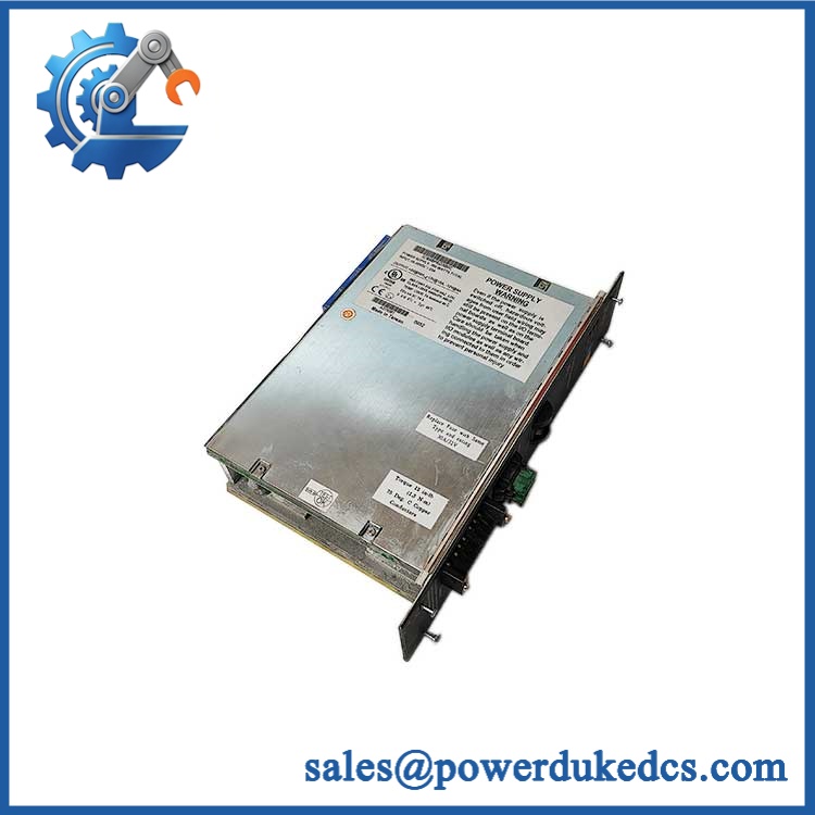
GE IC670MDL241J
Module 5: Quality Assurance SOP
Our pre-shipment inspection for a GE IC670MDL241J focuses on the 240 VAC input circuits, grouped architecture, indicator operation, and exact revision:
- OEM anti-counterfeit visual inspection — verify GE Fanuc markings, complete IC670MDL241J identification, revision information, PCB artwork, terminal interface, LEDs, and manufacturing labels.
- Revision capture — photograph the full module label and record the J hardware revision before testing.
- Terminal-block verification — confirm the module is paired with the correct GE Field Control terminal-block architecture used by the customer’s station.
- Mechanical inspection — inspect the housing, retaining screws, keying slots, terminal interface, connectors, and evidence of cracking, corrosion, or impact.
- PCB inspection — check input circuitry, resistors/capacitors, isolation components, solder joints, LEDs, contamination, and thermal discoloration.
- Controlled field-power test — apply a protected 240 VAC test source through an appropriate isolated fixture and verify the field-power indication.
- Power-on self-test (POST) — verify the PWR indicator, module startup behavior, and absence of abnormal current draw or diagnostic conditions.
- Sixteen-channel input test — apply controlled AC input signals to all 16 channels and verify correct state recognition.
- Group-isolation check — verify that the two eight-point groups behave according to the documented commoning arrangement and do not exhibit unintended cross-group interaction.
- Threshold verification — test representative channels at appropriate on/off transition levels using calibrated AC instrumentation.
- LED verification — confirm each input-status indicator accurately follows the associated field state.
- Input-current screening — verify representative channel input current remains within the documented operating range and does not show abnormal leakage.
- Genius Bus communication handshake verification — connect the module to a compatible Field Control Bus Interface Unit and verify correct station recognition and I/O-state exchange.
- Diagnostic verification — introduce a controlled input or communication fault where the test environment permits and confirm the expected diagnostic response.
- Extended operation test — operate multiple channels simultaneously while monitoring input stability, LED behavior, module temperature, and communication continuity.
- Configuration record — document part number, J revision, terminal-block type, test voltage, all-channel results, bus address, diagnostic results, and photographs.
- Final QC review — cross-check every identifier against the customer’s exact IC670MDL241J requirement.
- ESD packaging — protect the module and field interface against ESD, moisture, dust, and mechanical damage before shipment.
GE’s original Field Control documentation establishes the critical points for acceptance: IC670MDL241 = 16-point 240 VAC input, two groups, with the module itself powered from the BIU and the field circuits supplied separately.
Module 6: CRO-Driven Buyer FAQ
1. Is GE IC670MDL241J obsolete?
The IC670MDL241 family belongs to the legacy GE Genius Field Control platform and is now primarily encountered in installed-base maintenance. The exact J hardware revision should be matched when sourcing a replacement rather than ordering only by the family number.
2. What does actually do?
It is a 240 VAC, 16-point grouped discrete-input module. GE documentation identifies the architecture as two groups of eight inputs, intended for Field Control distributed I/O stations.
3. Is each input individually isolated?
No. The module uses a grouped-input architecture, with two groups of eight points. It should not be treated as equivalent to GE’s isolated 120 VAC input module IC670MDL233.
4. Does the module itself need a separate 240 VAC field supply?
Yes. GE documentation distinguishes the module’s internal supply from the external field supply. The BIU provides power for the module electronics, while the 240 VAC field input is supplied through the terminal block.
5. Can be hot-swapped?
Not universally. GE documents that only the newer IC670CHS101/102/103 terminal blocks, which have alignment tabs, support hot insertion/removal; the older IC670CHS001/002/003 terminal blocks do not. Therefore, hot replacement depends on the installed terminal-block generation and the approved maintenance procedure.
6. What warranty and technical support should I expect?
Warranty duration should be stated on the quotation for the exact physical module supplied. Technical support should cover part-number and revision verification, grouped-input wiring checks, 240 VAC input testing, terminal-block compatibility, Genius Bus diagnostics, and documented pre-shipment QA results. It should not substitute for plant electrical-safety procedures, PLC engineering, or field commissioning.











 Start Chat


