

Description
- Brand: GE Fanuc
- Full Model Number: IC670MDL640
- System/Series Family: Field Control Distributed I/O
- One-Sentence Core Function: 16-point discrete input module supporting both positive and negative 24 VDC logic
- Top 3 Hardcore Specs: 16 inputs; 0–30 VDC input range; 6 ms typical / 10 ms maximum response
- Stock Status: Stock condition and hardware revision to be confirmed
Module 3: Technical Product Introduction
A failed discrete input module can remove an entire group of field-status signals from a legacy Field Control installation. GE IC670MDL640 is a 24 VDC positive/negative logic discrete input module providing one group of 16 inputs. The module accepts either positive or negative logic, allowing the same hardware to monitor +24 VDC or −24 VDC field signals. Individual LEDs provide point-by-point status indication, while the PWR LED indicates the presence of field and backplane power. A separate Bus Interface Unit handles host-side data processing and configuration functions.
The electrical characteristics are well defined. The module supports a 0–30 VDC input range, with positive-logic ON at +15 to +30 VDC and negative-logic ON at −15 to −30 VDC. OFF-state ranges are 0 to +5 VDC and 0 to −5 VDC respectively. Input current is 3.0–8 mA in the ON state, with approximately 3 kΩ input impedance. Response time is 6 ms typical and 10 ms maximum for both ON and OFF transitions. The module draws approximately 75 mA typical and 83 mA maximum from the BIU power supply when all points are active.
Module 4: Application Scenarios & Field Realities
- For motor starters, valve limit switches, auxiliary contacts, and equipment permissives, the IC670MDL640 provides 16 discrete status points in one Field Control module position. Measure the voltage at the actual input terminal rather than assuming the nominal 24 VDC source remains available after field wiring and contact resistance.
- Where control cabinets use mixed signal polarity, the positive/negative logic capability can simplify field interfacing. The same module accepts positive or negative DC logic, but each circuit still needs to be wired according to its intended polarity and the correct terminal arrangement.
- For remote Field Control I/O installations, the module itself handles the electrical input interface while the Bus Interface Unit provides the host-facing processing and configuration functions. A loss of all 16 points should therefore prompt inspection of the BIU, terminal block, field supply, and cable path as well as the input module.
- During troubleshooting of intermittent discrete signals, the individual point LEDs are useful for separating field-side faults from host communication problems. A point LED that changes correctly while the host value remains unchanged directs attention toward the BIU or communication path rather than the input circuitry.
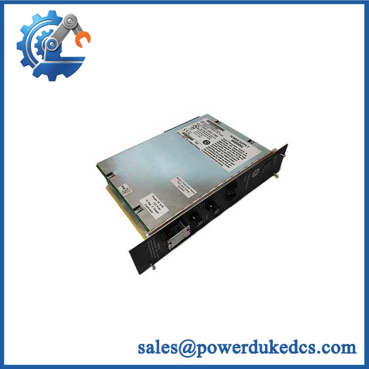
GE IC670MDL640
Module 5: Migration, Compatibility & Installation Traps
Replacement Matrix
Replacement Classification: Drop-in Replacement Within the Matching GE Field Control Configuration
A like-for-like IC670MDL640 replacement is appropriate when the existing installation uses the GE Field Control architecture, compatible I/O terminal block, BIU, cable assembly, and module keying arrangement. The module provides 16 positive/negative logic 24 VDC inputs and should be replaced with the same signal class unless an engineered wiring change has been approved.
IC670MDL640 → IC670MDL641: Hardware Modification Required. Both are positive/negative logic input modules, but IC670MDL641 is designed for 48 VDC operation rather than the 24 VDC interface of IC670MDL640.
Configuration Review Required. IC670MDL644 is a 24 VDC positive/negative fast discrete input module. Although the nominal voltage and point count are similar, its timing characteristics differ and should be matched to the application.
→ Generic 24 VDC digital input module: Hardware Modification Required. The Field Control terminal block, BIU interface, keying arrangement, and positive/negative logic behavior must all be compatible.
⚠️ Field Traps — Watch Out
1. Positive versus negative logic: The module supports both polarities, but the ON/OFF thresholds are polarity-specific. Positive logic requires +15 to +30 VDC for ON; negative logic requires −15 to −30 VDC. Do not assume a standard +24 VDC wiring diagram applies to every installation.
2. No isolation between individual points: The module specification provides isolation between the user input and logic, frame ground, and groups, but there is no isolation between individual points within the group. Field commoning therefore needs to be reviewed before connecting circuits from different supplies or references.
3. External field supply: The module receives power for its internal logic from the Field Processor/BIU, while an external 24 VDC supply is required for the input devices. A healthy PWR LED does not by itself prove that the field-side supply is correctly wired to every input.
4. Keying and terminal hardware: GE Field Control modules use configurable mechanical keying. Preserve the existing keying arrangement and verify the terminal block and cable assembly before insertion; a card that physically slides into the rack is not automatically the correct field interface.
Module 6: Quality Assurance SOP
Each GE should undergo a documented identification, electrical, and channel-level test before shipment.
- OEM identification visual inspection: Verify GE Fanuc markings, designation, serial number, revision information, module label, connector interface, and front-panel identification.
- System verification: Confirm compatibility with the GE Field Control Distributed I/O architecture and record the associated BIU, terminal block, and cable arrangement.
- Mechanical inspection: Examine the housing, connector, keying features, PCB, LED window, mounting surfaces, and accessible components for cracks, corrosion, contamination, or evidence of repair.
- Power verification: Install the module in an approved Field Control test arrangement and verify the internal logic supply and external field supply separately.
- Power-on self-test (POST): Confirm normal PWR indication and verify initialization through the associated BIU.
- 16-channel input test: Exercise all 16 inputs independently using a calibrated DC source and record the module indication and host-side input state.
- Positive-logic test: Verify representative inputs at 0–5 VDC OFF and +15–30 VDC ON conditions.
- Negative-logic test: Verify representative inputs at 0 to −5 VDC OFF and −15 to −30 VDC ON conditions.
- Input-current verification: Measure representative ON-state current and confirm behavior within the published 3.0–8 mA range.
- Input-impedance verification: Where authorized, verify representative input loading against the approximately 3 kΩ typical specification.
- Response-time test: Apply controlled state transitions and verify representative ON and OFF response within the 6 ms typical / 10 ms maximum specification.
- LED verification: Confirm all 16 individual point indicators respond correctly to the corresponding input state.
- BIU communication test: Verify that the associated Bus Interface Unit correctly transfers all 16 input states to the host controller.
- Isolation verification: Where required by the approved service procedure, verify field-to-logic and field-to-ground isolation without applying inappropriate voltage between individual commoned points.
- Field-supply test: Confirm the external 24 VDC source remains within the required range under representative loading.
- Noise and stability test: Cycle representative inputs while monitoring false transitions, LED behavior, BIU data, and supply stability.
- Extended operation test: Keep representative points active and inactive over an extended period while monitoring input recognition and host communication.
- Final QC record: Retain identification photographs, revision information, terminal-block reference, all 16 channel results, positive/negative logic test data, timing measurements, BIU communication results, and final QC approval.
The is a 16-point Field Control discrete input module for 24 VDC positive or negative logic, with a 0–30 VDC input range, 3 kΩ typical input impedance, 3–8 mA ON-state current, and 6 ms typical / 10 ms maximum response time.
Its defining feature is the ability to accept either positive or negative DC logic, while the individual inputs within the group are not isolated from one another. The module also depends on the associated BIU, terminal block, cable assembly, mechanical keying, and external field supply, so those interfaces should be verified together before a replacement is released for a production Field Control installation.











 Start Chat


