

Description
- Brand GE Fanuc / Emerson
- Full Model Number IC670MDL730
- System/Series Family GE Fanuc Field Control Distributed I/O
- Core Function 8-point 24 VDC positive-logic discrete output module with electronic short-circuit protection
- Top 3 Hardcore Specs 8 outputs | 18–30 VDC user supply | 2.0 A maximum per point
- Stock Status New Surplus — verify terminal base, BIU revision, keying, and field-power arrangement before shipment
Module 3: Technical Product Introduction
A failed output block can remove several actuator commands at once, especially in older Field Control installations where one module handles a group of eight field loads. GE IC670MDL730 is an 8-point 24 VDC positive-logic discrete output module with electronic short-circuit and overcurrent protection on each channel. The GE Fanuc technical data sheet specifies an external DC source for the loads, while the module’s internal logic power comes from the Bus Interface Unit (BIU). Each output has individual green status and yellow fault indication.
The electrical limits are well defined: user input supply is 18–30 VDC, with 24 VDC nominal, while the output voltage range is 17.5–29.5 VDC. Continuous load is rated at 2.0 A maximum per point and 8 A maximum per module. Each channel can withstand an inrush of up to 10 A for 10 ms, with typical overcurrent trip behavior around 2.25–2.75 A. Output response is specified at 500 µs maximum for both turn-on and turn-off, with short-circuit response and automatic retry circuitry.
Module 4: Application Scenarios & Field Realities
- Inside legacy GE Fanuc Field Control I/O stations, IC670MDL730 provides eight discrete output channels for 24 VDC field devices. Typical loads include relays, pilot devices, solenoids, and other DC actuators within the specified current limits.
- When one output repeatedly reports a fault, inspect the connected load first. The module uses electronic overcurrent and short-circuit protection, so a downstream short can cause the affected channel to trip rather than immediately indicating a failed module. Individual yellow fault LEDs help localize the affected point.
- For installations with high starting current, the documented 10 A maximum inrush for 10 ms provides useful design margin, but the actual load should still be evaluated. Solenoid coils and contactors can have very different startup profiles depending on suppression and operating conditions.
- During Field Control maintenance, remember that the module itself does not perform the higher-level control processing. Configuration, fault reporting, and host communication are handled by the Bus Interface Unit or elsewhere in the system. The GE data sheet states that a compatible BIU is required to obtain the module’s output data from the host.
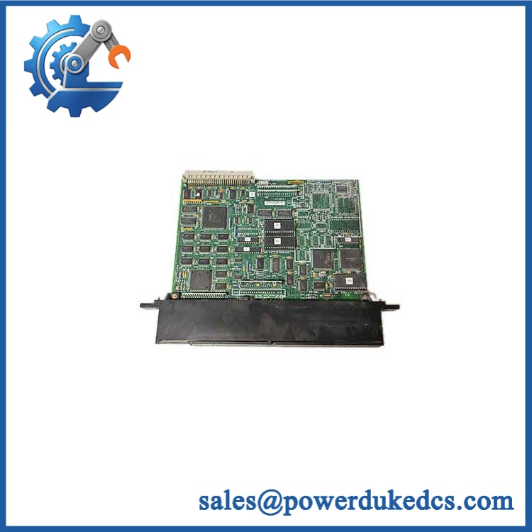
GE IC670MDL730
Module 5: Migration, Compatibility & Installation Traps
Replacement Matrix
| Replacement Status | Engineering Assessment |
|---|---|
| Drop-in Replacement | Yes, for a like-for-like IC670MDL730 installation using the correct Field Control terminal base, BIU, keying, and external 24 VDC load supply. |
| Software Compatible | Generally yes for an exact replacement. The module has no user application firmware, but the Field Control host/BIU configuration and output assignments must be retained. |
| Hardware Modification Required | Normally no for an exact replacement. Modification may be required when changing output voltage class, terminal-base architecture, BIU generation, or module family. |
⚠️ Field Traps: Watch Out
IC670MDL730 is an output module, not an input module. Several current web listings classify the part incorrectly, but the GE Fanuc GFK-1288B data sheet explicitly identifies IC670MDL730 as a 24 VDC Positive Logic Electronic Short Circuit Protection Output Module with eight outputs.
Verify the external load supply. The module’s own logic power comes from the BIU, but the field loads require an external DC power source. A new module can therefore appear healthy at the logic level while all field outputs remain inactive because the user supply is missing.
Do not exceed the 8 A module total. Each point is rated up to 2 A, but the aggregate continuous load is limited to 8 A per module. Four channels at their individual maximums would already consume the full module rating.
Check BIU compatibility. The technical data specifies that must be used with Genius BIU IC670GBI002 revision 2.10 or later; Profibus and Interbus-S BIUs have their own minimum version requirements. A correct output card paired with an incompatible BIU can create a system-level failure.
Respect the module’s group architecture. There are 8 outputs in one group, with no isolation between individual points within that group. Isolation is provided between the user terminal group, logic, frame ground, and other applicable groups.
Keying is part of the replacement check. GE documentation provides optional keying locations for the MDL730. Preserve the original keying arrangement so that the replacement cannot be inadvertently inserted into an incompatible terminal-base position.
Module 6: Quality Assurance SOP
A surplus should undergo channel-by-channel load testing together with BIU and terminal-base verification. A simple power-on check is not enough.
- OEM anti-counterfeit visual inspection: Verify GE Fanuc identification, exact marking, product label, front-panel LED arrangement, connector geometry, PCB revision, and visible manufacturing codes against controlled references.
- Part-number and traceability check: Record the complete number, hardware revision, serial/date code, terminal-base reference, and BIU model/revision.
- Mechanical inspection: Examine the housing, terminal interface, connector pins, keying features, mounting surfaces, and PCB for cracks, contamination, corrosion, bent contacts, or unauthorized rework.
- BIU compatibility verification: Confirm the installed test system uses IC670GBI002 revision 2.10 or later, or an approved Profibus/Interbus-S BIU version meeting the documented compatibility requirement.
- Power-on self-test (POST): Install the module in a known-good Field Control station and verify expected PWR, point-status, and fault-indicator behavior.
- User-supply verification: Apply a controlled 18–30 VDC user supply, using 24 VDC nominal as the normal test point, and verify stable module operation.
- Output-voltage verification: Measure representative channels under controlled load and verify operation within the documented 17.5–29.5 VDC output range.
- Eight-channel functional test: Command each of the eight outputs independently and verify correct green status indication and output state.
- Load-current test: Exercise representative channels at controlled currents below 2.0 A per point, while ensuring total module current remains below 8 A.
- Inrush test: Where the approved fixture permits, apply a controlled transient representative of the documented 10 A maximum for 10 ms and verify the output remains within the expected protection behavior.
- Overcurrent-trip test: Use a current-limited laboratory setup to verify the channel’s electronic protection response around the documented 2.25–2.75 A nominal trip region.
- Short-circuit protection test: Apply only controlled, current-limited fault conditions and confirm the affected channel produces the expected yellow fault indication and recovery behavior.
- Automatic-retry verification: Verify that the electronic protection and retry sequence operate as documented after a controlled fault is removed.
- Turn-on timing test: Measure controlled output transitions and confirm the documented 500 µs maximum turn-on response where the test fixture supports dynamic measurement.
- Turn-off timing test: Measure controlled output release and verify the documented 500 µs maximum turn-off response.
- Leakage-current test: Measure Off-state leakage and verify it remains below the documented 0.5 mA maximum at 30 VDC.
- Isolation verification: Verify user-terminal-to-logic, user-terminal-to-frame-ground, and applicable group isolation using the approved test method; the specification gives 250 VAC continuous / 1500 VAC for 1 minute for the applicable isolation paths.
- LED verification: Confirm individual green output-status LEDs and yellow fault LEDs correspond to the correct physical channels.
- Terminal-base verification: Confirm correct mating, terminal assignment, and field-supply routing through the installed base.
- Communication handshake verification: Verify successful host-to-BIU-to-module output-command transfer. The MDL730 itself does not contain the higher-level host processor; the BIU performs the required interface processing.
- Field-load simulation: Test representative relay or solenoid loads and confirm stable operation through the complete module/terminal-base path.
- Extended-run test: Operate representative channels under continuous load while monitoring output stability, fault indications, current draw, connector temperature, and intermittent trips.
- Final QC record: Document BIU revision, supply voltage, eight channel results, output voltage, load currents, inrush response, overcurrent behavior, leakage, isolation, LED status, timing results, extended-run observations, traceability, and packaging condition.
Technical Identification Note: GE Fanuc’s GFK-1288B documentation identifies as a 24 VDC positive-logic electronic short-circuit-protection output module with 8 discrete outputs, 18–30 VDC user supply, 2.0 A maximum continuous current per point, 8 A maximum per module, 10 A maximum inrush for 10 ms, and 500 µs maximum turn-on/turn-off response. The module requires an appropriate Field Control Bus Interface Unit, with Genius IC670GBI002 revision 2.10 or later explicitly identified in the compatibility documentation.











 Start Chat


