

Description
- Brand: GE Fanuc
- Full Model Number: IC670MDL740J
- System/Series Family: Field Control Distributed I/O and Control System
- One-Sentence Core Function: 16-point positive-logic sourcing output module for switching 10–30 VDC loads
- Top 3 Hardcore Specs: 16 grouped outputs; 0.5 A maximum per point; 4 A maximum per module
- Stock Status: New Surplus / Fully Tested Refurbished — verify revision suffix J, BIU compatibility, and terminal-block configuration before shipment
Module 3: Technical Product Introduction
When a decentralized Field Control node must energize multiple DC loads, the output module has to handle both the field voltage and the aggregate load without creating nuisance faults. The GE IC670MDL740J is the revision-designated form of the IC670MDL740 12/24 VDC Positive Output Module, providing 16 positive-logic, sourcing outputs. Each output switches the load toward the positive side of the external DC supply, with a documented 10–30 VDC user supply range, 24 VDC nominal voltage, and 0.5 A maximum per point.
The module uses one grouped output arrangement rather than sixteen individually isolated channels. Total load current is limited to 4 A per module, with a documented 0.5 V maximum output-voltage drop and 0.5 mA leakage at 30 VDC. Under a 0.5 A resistive load, the specified ON and OFF response times are approximately 200 µs maximum. Protection is provided by a 5 A, 250 V, 5 × 20 mm slow-acting fuse associated with the common output supply.
Module 4: Application Scenarios & Field Realities
- On conveyor, packaging, and machine-control nodes, the IC670MDL740J can switch pilot lamps, relay coils, solenoids, and similar low-current DC loads. The 0.5 A point rating is suitable for many conventional pilot-duty loads, but coil inrush still needs to be checked rather than assumed.
- When several outputs drop out together, inspect the external user supply and the common output fuse first. The module monitors the external supply and interprets a supply condition below approximately 9.8 VDC as a fault reported through the Bus Interface Unit.
- During Field Control cabinet replacement, verify the BIU revision as well as the output module. GE documentation identifies the IC670MDL740 as a Field Control module installed with a Bus Interface Unit; other Field Control products have minimum BIU revision requirements, so cabinet-level compatibility should be checked rather than assumed from the module suffix alone.
- Where a load exceeds the 0.5 A point rating, do not parallel outputs casually to obtain more current. A properly selected interposing relay or higher-current output module is the correct engineering solution. The documented Field Control range includes alternatives such as IC670MDL730 and IC670MDL742 with different output characteristics.
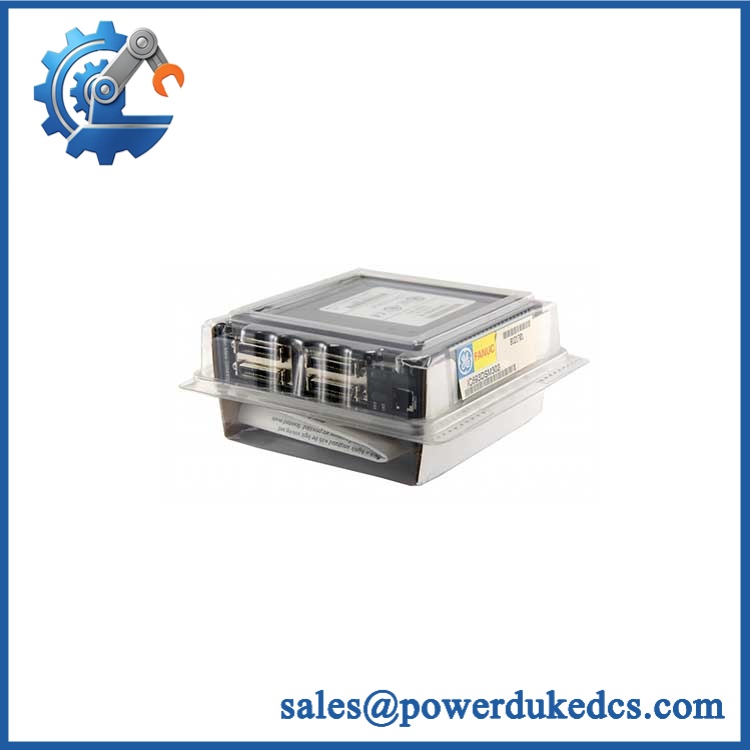
GE IC670MDL740J
Module 5: Migration, Compatibility & Installation Traps
Replacement Matrix
| Replacement Type | Assessment |
|---|---|
| Drop-in Replacement | Yes, for an exact IC670MDL740 replacement with matching Field Control hardware and wiring |
| Software Compatible | Normally yes within the Field Control configuration, but BIU revision and node configuration should be verified |
| Hardware Modification Required | Normally no for a like-for-like replacement; external supply, terminal block, fuse arrangement, and load grouping must match |
⚠️ Field Traps — Watch Out
1. The “J” suffix should be preserved in stock records.
The technical documentation identifies the base IC670MDL740; your supplied IC670MDL740J should therefore be matched by the physical label and revision marking before substitution. Do not remove the suffix from the inventory description merely because the base datasheet uses IC670MDL740.
2. Outputs are grouped, not individually isolated.
The module provides one group of 16 positive-logic outputs. There is no individual point-to-point isolation within that group, so common wiring and external supply integrity can affect multiple channels.
3. Respect the 4 A total module limit.
Even if each individual load is below 0.5 A, the combined load cannot simply be treated as unlimited. The published module rating is 4 A maximum per module.
4. The external field supply is separate from module logic power.
GE documentation states that the module’s own logic power comes from the Bus Interface Unit, while an external DC source powers the output switches and loads. Mixing these two supply paths during troubleshooting can lead to incorrect fault diagnosis.
Module 6: Quality Assurance SOP
- OEM anti-counterfeit visual inspection — inspect GE Fanuc identification, IC670MDL740J marking, label, front-panel legends, LED indicators, connectors, housing, and visible manufacturing details.
- Exact part-number verification — confirm IC670MDL740J character-for-character against the purchase order and physical module label. Record the base IC670MDL740 designation separately where required by the service documentation.
- Revision verification — photograph the complete label, serial information, hardware revision, and any date/manufacturing codes before testing.
- Field Control architecture check — verify the intended Bus Interface Unit, I/O Terminal Block, and cabinet arrangement. Confirm that the installed node is compatible with the module revision.
- Mechanical inspection — inspect the backplane/BIU connector, terminal-block interface, enclosure, mounting features, fuse area, and PCB surfaces for bent contacts, corrosion, contamination, cracks, or impact damage.
- Power-on self-test (POST) — install the module in an approved Field Control test setup and energize the system. Record power/status LED behavior, diagnostic indications, current draw, and abnormal heating.
- User-supply verification — apply a controlled 10–30 VDC external output supply and verify stable operation at representative points. Confirm the supply remains above the documented fault-monitoring threshold.
- 16-channel output simulation — operate all available output points individually using calibrated DC loads. Record commanded state, measured output voltage, load current, and diagnostic status.
- Load-current validation — verify representative outputs at appropriate fractions of the 0.5 A per-point rating while maintaining total module demand below 4 A.
- Response-time verification — where the test fixture supports timing measurement, verify ON and OFF transitions against the documented 200 µs maximum response under the specified resistive-load condition.
- Output-voltage-drop verification — measure representative channels under load and confirm the voltage drop remains within the documented 0.5 V maximum characteristic.
- Leakage-current verification — with the output OFF and the specified DC supply applied, measure representative channels and verify leakage against the documented 0.5 mA at 30 VDC characteristic.
- Fuse and protection verification — confirm the installed protection uses the documented 5 A, 250 V, 5 × 20 mm slow-acting fuse and inspect the common output-supply path.
- Field Control communication verification — connect the module to a compatible BIU and verify correct node/module recognition and output-command exchange through the Field Control architecture.
- Terminal-path verification — perform point-to-point continuity checks from module terminals through the installed terminal block to the controlled loads. Preserve the original 1–16 channel assignment.
- Fault simulation — use an approved test fixture to simulate loss of external output supply or other permissible field faults and confirm the expected BIU/module diagnostic response.
- Final QC and packaging — record model and revision, 16-channel test results, supply measurements, protection checks, BIU configuration, photographs, ESD protection, and packaging condition before shipment.
Engineering note: The should be cataloged as a revision-specific 12/24 VDC positive-logic output module. The documented base module provides 16 grouped sourcing outputs, 10–30 VDC user input, 0.5 A maximum per point, 4 A maximum per module, 250 VAC continuous / 1500 VAC for one minute isolation from logic and frame ground, and approximately 200 µs maximum ON/OFF response under the specified resistive-load test condition.











 Start Chat


