

Description
- Brand: GE Fanuc
- Full Model Number: IC693ALG221
- System/Series Family: Series 90-30 PLC
- One-Sentence Core Function: Four-channel analog current input module converting 4–20 mA or 0–20 mA field signals into PLC digital data
- Top 3 Hardcore Specs: 4 channels; 12-bit resolution; 2 ms update rate
- Stock Status: New Surplus / Fully Tested Refurbished — verify terminal-board jumper configuration before shipment
Module 3: Technical Product Introduction
A bad analog input does not always look like a failed transmitter. When a pressure, flow, temperature, or level value is frozen or scaled incorrectly, the Series 90-30 I/O card and its terminal-board configuration are both worth checking. The GE IC693ALG221 is a 4-channel analog current input module for the Series 90-30 PLC. It accepts 4–20 mA by default or 0–20 mA when the appropriate terminal-board jumper is installed, converting each field current signal into PLC digital data.
Each channel uses a 12-bit A/D converter, with a conversion time of approximately 0.5 ms per channel and an overall update rate of 2 ms for all four channels. The input impedance is 250 Ω, input filter response is 325 Hz, and field-to-logic isolation is specified at 1500 V. In the default 4–20 mA configuration, 4 mA corresponds to a digital count of 0 and 20 mA to 32,000; the 0–20 mA configuration likewise scales 0 to 20 mA across 0 to 32,000 counts.
Module 4: Application Scenarios & Field Realities
- On a Series 90-30 process skid, the IC693ALG221 can acquire current-loop signals from pressure, flow, level, and temperature transmitters. When one process value is wrong, measure the actual loop current first; a transmitter producing a correct 12 mA signal with an incorrect PLC value points the investigation toward the input path.
- During replacement of an existing ALG221, check the terminal-board jumper arrangement before reconnecting the field wires. The default configuration is 4–20 mA, while adding the specified jumper changes the range to 0–20 mA. The jumper arrangement applies to channels 1–2 and 3–4 as separate groups.
- For brownfield cabinets with long analog runs, inspect shielding, common wiring, and loop resistance alongside the module. The card has 250 Ω input impedance, so the transmitter’s compliance voltage must remain sufficient for the complete loop.
- When several analog values become abnormal together, check the terminal board and module supply before replacing transmitters individually. The module provides four channels, with field-to-logic isolation intended to limit the effect of external electrical conditions on the PLC logic side.
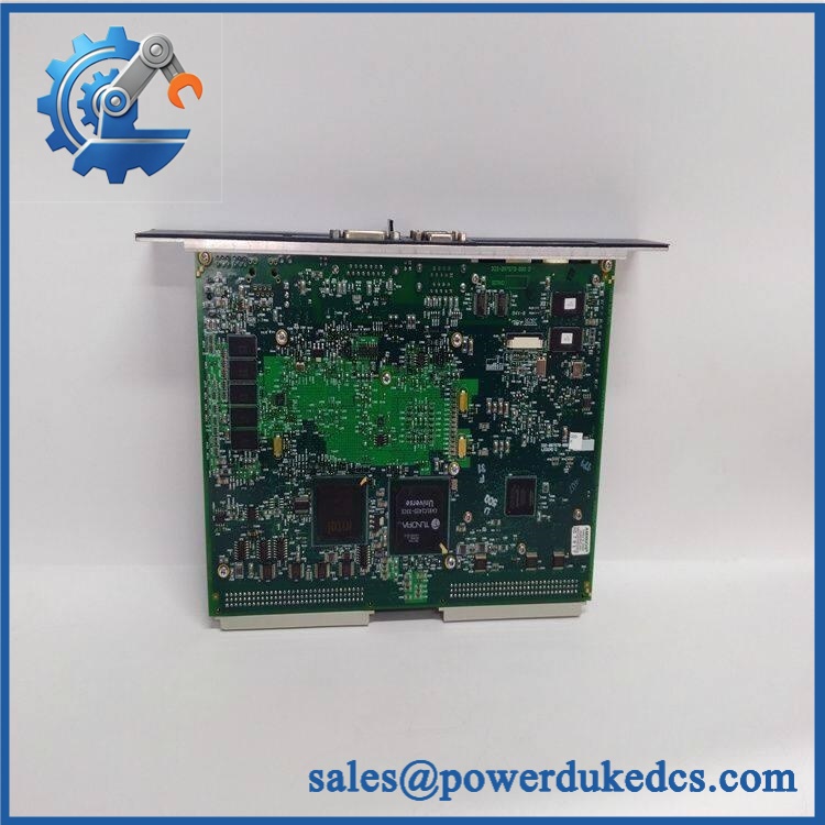
GE IC693ALG221
Module 5: Migration, Compatibility & Installation Traps
Replacement Matrix
| Replacement Type | Assessment |
|---|---|
| Drop-in Replacement | Yes, for an exact IC693ALG221 replacement in a compatible Series 90-30 configuration |
| Software Compatible | Normally yes within the Series 90-30 I/O configuration, but channel addressing and range configuration must be verified |
| Hardware Modification Required | Normally no for a like-for-like replacement; terminal-board jumper settings and field wiring must match |
⚠️ Field Traps — Watch Out
1. The 4–20 mA / 0–20 mA selection is not simply a software setting.
The documented default is 4–20 mA. The module changes to 0–20 mA through a jumper on the I/O terminal board, with one jumper serving channels 1–2 and another serving channels 3–4.
2. Do not connect voltage signals directly.
The IC693ALG221 is a current-input module. Its documented input ranges are 4–20 mA and 0–20 mA; it is not the Series 90-30 voltage-input equivalent.
3. Preserve the digital scaling convention.
In the 4–20 mA range, 4 mA = 0 counts and 20 mA = 32,000 counts. In the 0–20 mA range, 0 mA = 0 counts and 20 mA = 32,000 counts. A mismatch between the physical jumper state and the PLC scaling can produce plausible but incorrect process values.
4. Check loop burden before commissioning.
The module’s 250 Ω input impedance adds to the transmitter loop burden. Long cable runs, additional indicators, barriers, or other series components can push the transmitter beyond its available compliance voltage.
Module 6: Quality Assurance SOP
- OEM anti-counterfeit visual inspection — inspect GE Fanuc identification, IC693ALG221 marking, terminal-board interface, housing, labels, LEDs, and visible manufacturing details.
- Exact part-number verification — confirm character-for-character against the purchase order and physical module label.
- Series 90-30 compatibility check — verify the target rack/baseplate and I/O slot before installation.
- Terminal-board jumper verification — inspect and photograph the range jumpers for channels 1–2 and 3–4. Record whether each group is configured for 4–20 mA or 0–20 mA.
- Mechanical inspection — inspect the module connector, terminal-board interface, housing, mounting hardware, LEDs, PCB surfaces, and contacts for oxidation, contamination, cracks, or bent pins.
- Power-on self-test (POST) — install the module in an approved Series 90-30 test rack and energize under controlled conditions. Record power indication, diagnostic behavior, current draw, and abnormal temperature rise.
- Four-channel analog simulation — apply calibrated current signals to each input. Test representative points at 0%, 25%, 50%, 75%, and 100% of the confirmed input range.
- 4–20 mA verification — where configured for the default range, verify that 4 mA produces approximately 0 counts and 20 mA approximately 32,000 counts in the PLC input register.
- 0–20 mA verification — where configured for the alternate range, verify 0 mA = approximately 0 counts and 20 mA = approximately 32,000 counts.
- Four-channel verification — test all four channels independently and record applied current, PLC count, channel number, and diagnostic result.
- Conversion-rate verification — where the laboratory fixture supports timing measurements, verify the approximately 0.5 ms per-channel conversion and 2 ms all-channel update characteristics.
- Input-impedance verification — verify the 250 Ω input path using the approved test procedure and calibrated instrumentation.
- Isolation verification — where required by the applicable maintenance procedure, verify field-to-logic isolation against the documented 1500 V specification. Use an approved tester and controlled test conditions.
- Noise and stability verification — monitor representative analog channels for abnormal drift, oscillation, or excessive noise under stable current-source conditions.
- PLC data verification — confirm correct
%AIregister updates, channel addressing, and application scaling in the Series 90-30 controller. - Communication handshake verification — not applicable as a standalone Ethernet or serial test. Verify the module through the Series 90-30 backplane and controller I/O scan instead.
- Final QC and packaging — document model number, jumper configuration, four-channel test results, scaling results, isolation test status, label photographs, ESD protection, and packaging condition before shipment.
Engineering note: The is a well-documented Series 90-30 4-channel analog current input module. It supports 4–20 mA or 0–20 mA, provides 12-bit resolution, updates all four channels in approximately 2 ms, uses 250 Ω input impedance, and provides 1500 V field-to-logic isolation. The most important replacement check is the terminal-board jumper configuration, because it determines whether channels 1–2 and 3–4 operate in the 4–20 mA or 0–20 mA range.











 Start Chat


