

Description
- Brand: GE Energy
- Full Model Number: IS200AEPAH1BHC / IS215WEPAH2B
- System/Series Family: Mark VI / Mark VIe Wind Energy Control
- Core Function: Wind turbine pitch-axis control and field I/O interface
- Top 3 Hardcore Specs: 8 analog inputs | 20 discrete inputs | 2 RS-485 interfaces
- Additional I/O: Incremental encoder input | Analog output | 2 discrete outputs | 9 relay outputs | 2 PWM outputs
- Control Function: AEPA / WEPA wind pitch-axis control
- Stock Status: New surplus, factory sealed, or fully tested refurbished subject to exact hardware confirmation
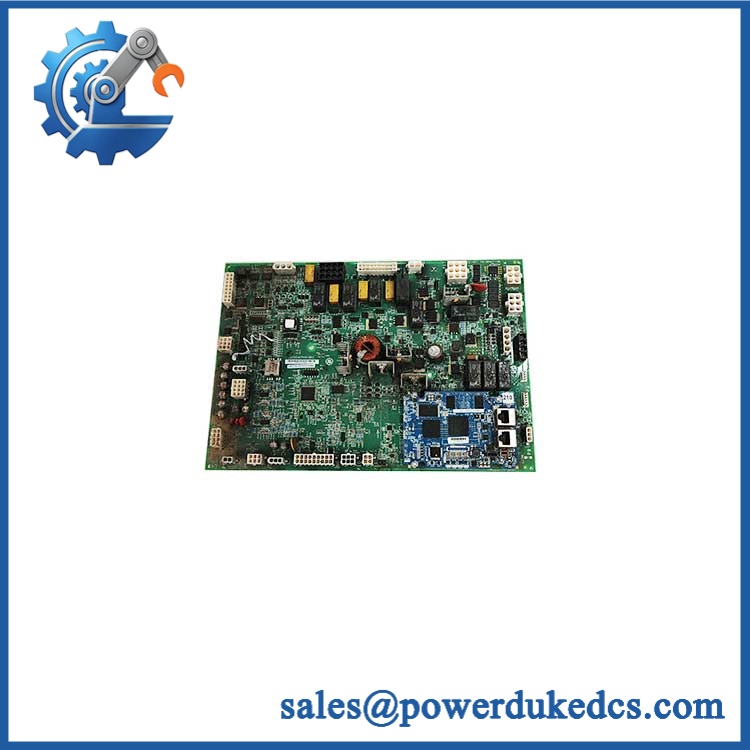
The IS200AEPAH1BHC and IS215WEPAH2B references belong to GE Energy wind-turbine pitch-axis control hardware. GE-related service records associate the AEPAH1BHC assembly with the IS215WEPAH2 family, while GE Energy lifecycle documentation identifies IS215WEPAH2B as a 30 Nm non-CANBus wind pitch-axis control board.
Module 3: Technical Product Introduction
A pitch-axis controller failure directly affects turbine blade positioning, so the replacement has to match more than the PCB outline. The IS200AEPAH1BHC / IS215WEPAH2B assembly is associated with GE Energy’s wind pitch-axis control architecture and the Mark VIe control system. The IS215WEPAH2B is documented as a 30 Nm non-CANBus WEPA board, while the IS200AEPAH1BHC is associated with the AEPA hardware within this assembly family.
The I/O density is significant for field replacement. Published technical records list 8 analog inputs, 1 incremental encoder input, 1 additional analog input, 20 discrete inputs, 2 discrete outputs, 9 relay outputs, 2 RS-485 interfaces, and 2 PWM control outputs for the IS215WEPAH2B. The board is also described as incorporating AEPA and BPPC daughterboard hardware. Software frame-rate options of 10, 20, and 40 ms are reported for the WEPAH2B configuration.
Module 4: Application Scenarios & Field Realities
- On wind turbines using 30 Nm pitch systems, the WEPAH2B provides the controller-side interface for pitch-axis signals and actuator control. During a failure investigation, check encoder feedback, supply conditions, and actuator wiring before concluding that the PCB itself has failed.
- For non-CANBus pitch architectures, the exact H2B configuration matters. GE lifecycle documentation distinguishes the H2B from H2A and identifies H2B as the available replacement for the older IS215WEPAH2A in the applicable product family.
- During turbine maintenance, document every connector, jumper, board revision, and daughterboard before removal. The assembly contains multiple signal interfaces, so a single connector-position error can affect pitch feedback or actuator control.
- Where encoder feedback is involved, verify the signal path independently before replacing the controller. An encoder fault, damaged cable, or incorrect termination can present as a controller or pitch-axis fault even when the board passes bench testing.
GE IS200AEPAH1BHC IS215WEPAH2B
Module 5: Migration, Compatibility & Installation Traps
Replacement Matrix
| Replacement Type | Assessment | Engineering Requirement |
|---|---|---|
| Drop-in Replacement | Potentially yes for a confirmed IS200AEPAH1BHC / IS215WEPAH2B configuration | Match complete board references, revision, daughterboards, connectors, and pitch-system rating |
| Software Compatible | Configuration-dependent | Verify Mark VIe application, frame rate, pitch parameters, and controller configuration |
| Hardware Modification Required | Potentially required when changing between CANBus and non-CANBus architectures | Confirm the installed pitch-axis communication architecture before substitution |
Field Traps — Watch Out
1. CANBus versus non-CANBus: GE’s lifecycle documentation separates the IS215WEPAH1 CANBus family from the IS215WEPAH2 non-CANBus family. Do not substitute a visually similar H1-series board for an H2-series installation without engineering verification.
2. H2A versus H2B: The same GE document identifies as an obsolete-to-available catalog transition. That does not mean every installed H2A configuration can be replaced without checking the machine’s application software, board revision, and associated hardware.
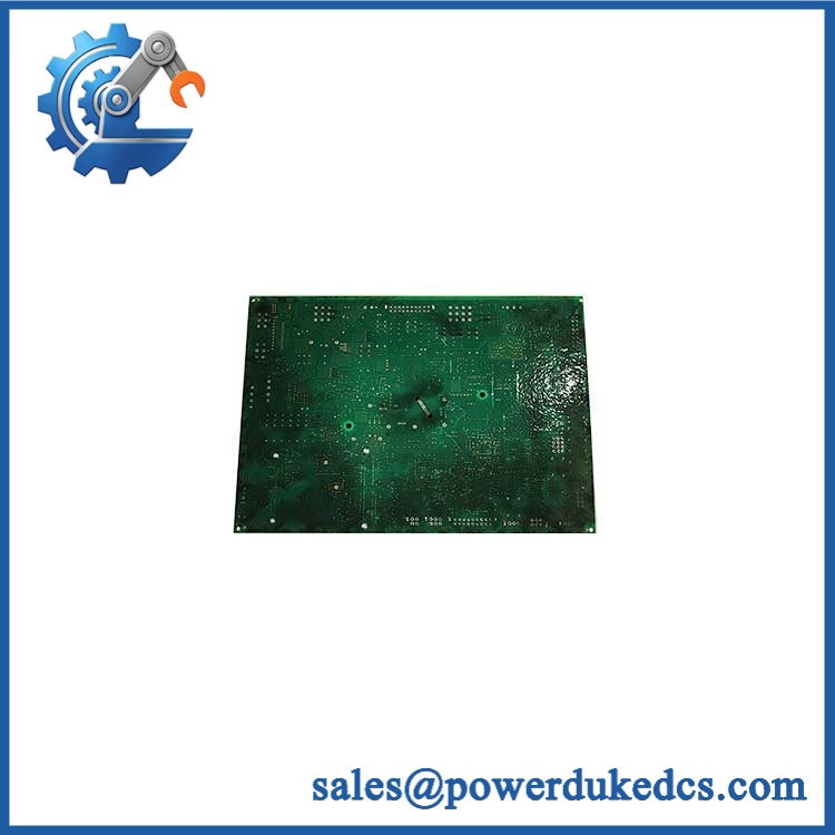
3. Daughterboard configuration: The is reported as incorporating AEPAH1B and BPPC-related daughterboard hardware. Verify the actual assembly configuration before ordering a bare PCB as a substitute for a complete assembly.
4. Pitch-axis feedback: The incremental encoder input and PWM outputs are part of the control loop. Before commissioning, verify encoder direction, feedback scaling, actuator command polarity, and pitch-limit/interlock behavior. Do not judge compatibility from a successful board power-up alone.
GE IS200AEPAH1BHC IS215WEPAH2B
Module 6: Quality Assurance SOP
Before shipment, each GE IS200AEPAH1BHC / IS215WEPAH2B assembly should undergo a documented inspection sequence appropriate to the available Mark VIe wind-control test equipment.
- Step 1 — Part-number verification: Record , , all visible GE board numbers, revision markings, daughterboard numbers, and serial information.
- Step 2 — OEM anti-counterfeit visual inspection: Inspect GE labels, PCB artwork, component markings, connectors, terminal interfaces, daughterboards, fasteners, and manufacturing identifiers. Photograph all identification markings.
- Step 3 — Physical condition inspection: Check for corrosion, contamination, cracked components, damaged connectors, bent contacts, loose hardware, PCB delamination, and evidence of previous unauthorized repair.
- Step 4 — Power-rail verification: Confirm the correct Mark VIe test-fixture supply before energization. Measure the supply at the board interface and check for abnormal current draw.
- Step 5 — Power-on self-test (POST): Energize the assembly under controlled conditions and record startup behavior, status LEDs, diagnostic indications, and controller initialization.
- Step 6 — Analog-input verification: Apply representative calibrated signals to selected analog channels and verify that the expected values are detected correctly.
- Step 7 — Encoder-input verification: Where a suitable simulator is available, exercise the incremental encoder input and confirm correct feedback detection and direction response.
- Step 8 — Digital I/O verification: Test representative discrete inputs, discrete outputs, relay outputs, and PWM control outputs. Record the observed state of each tested channel.
- Step 9 — Communication handshake verification: Test both RS-485 interfaces where the appropriate equipment is available and confirm expected communication response.
- Step 10 — Configuration verification: Confirm the tested assembly corresponds to the customer’s pitch-axis architecture, including CANBus/non-CANBus arrangement, board revision, daughterboard configuration, and software frame-rate requirements.
- Step 11 — Final photographic record: Photograph the complete assembly, model labels, daughterboards, connectors, revision markings, and final packaging.
QA release criterion: A successful power-up does not establish pitch-control compatibility. A fully tested unit should have documented I/O, encoder, communication, and relevant output checks. For turbine service, final commissioning should additionally verify pitch feedback, actuator response, limits, interlocks, and the installed Mark VIe application configuration.











 Start Chat


