

Description
- Brand: GE General Electric
- Full Model Number: IS200EGPAG1BCA
- Lifecycle Status: Obsolete / Legacy
- Core Function: EX2100 Gate Pulse Amplifier Board
- Top 3 Technical Specs: Up to 6 SCR gate-firing channels; nominal 125 VDC supply; 5 onboard configuration jumpers
- System: GE EX2100 Excitation Control
- Board Type: EGPA Gate Pulse Amplifier Board
- Primary Interface: ESEL control commands to power-conversion bridge
- Monitoring Inputs: Bridge current conduction; bridge temperature; fan/airflow; line-filter fuse status
- Status Indication: Green and red onboard LEDs
- Configuration: Jumper-dependent hardware settings
- Stock & Condition: Exact stock confirmation required; New Surplus / Tested Refurbished; Emergency shipping subject to warehouse cutoff
GE technical references identify IS200EGPAG1BCA as an EGPA Gate Pulse Amplifier Board for the EX2100 excitation-control architecture. The board receives gate commands from the ESEL and drives firing signals for up to six SCRs while also handling bridge monitoring inputs.
Module 3: Obsolescence & Supply Chain Deep Dive
An unavailable IS200EGPAG1BCA can keep an EX2100 excitation system offline even when the generator, power bridge, and wider control cabinet remain serviceable. The EGPA is the control-to-power-bridge interface responsible for conditioning gate commands and driving up to six SCR gate circuits. It also receives bridge current-conduction, temperature, fan/airflow, and line-filter fuse-status signals, so a failed board can affect both firing control and diagnostic visibility.
For TCO, an exact EGPA replacement can preserve the existing EX2100 bridge, ESEL interface, EPDM power architecture, cabinet wiring, and generator excitation configuration. That avoids the engineering and outage costs associated with replacing an entire excitation controller for a board-level failure. The key procurement requirement is revision and jumper matching: IS200EGPAG1BCA is not interchangeable with every IS200EGPA variant, and the board’s field configuration must be reproduced before commissioning. (Legacy inventory can remove a long sourcing delay when the generator is already in an outage window.)
Module 4: Compatibility & Replacement Matrix
| Approval Item | Engineering Assessment |
|---|---|
| Exact Part Replacement | Drop-in Replacement when the installed board is IS200EGPAG1BCA and the EX2100 configuration matches |
| Software Compatibility | Configuration-dependent; verify ESEL commands, cabinet configuration, and associated power-bridge setup |
| Firmware Flash | Not normally the primary board-replacement action; verify system revision before commissioning |
| Hardware Modification | Normally none for an exact board/revision match |
| Gate Outputs | Up to 6 SCR gate-firing channels |
| Nominal Supply | 125 VDC from EPDM |
| Configuration Hardware | 5 onboard jumpers |
| Monitoring Inputs | Bridge current, temperature, fan/airflow, line-filter fuse status |
| Estimated Physical Swap | 1–3 hours |
| Engineering / Commissioning Allowance | 500–1,500 planning range |
| Post-Replacement Testing | Mandatory for gate firing, bridge feedback, alarms, and protection interlocks |
GE-related technical references describe the EGPA as the interface between the ESEL control commands and the power-conversion bridge, with a nominal 125 VDC supply from the EPDM. The board also contains configurable jumpers and multiple status/monitoring circuits.
⚠️ Field Traps — Watch Out
- H1B Revision / Suffix Match: Do not substitute another EGPA board simply because the base designation is similar. Match IS200EGPAG1BCA character-for-character and document the installed hardware revision before removal.
- Jumper Configuration: The board has five onboard configurable jumpers. Photograph and record the original jumper positions; an incorrect setting can alter fan, temperature, or related monitoring behavior.
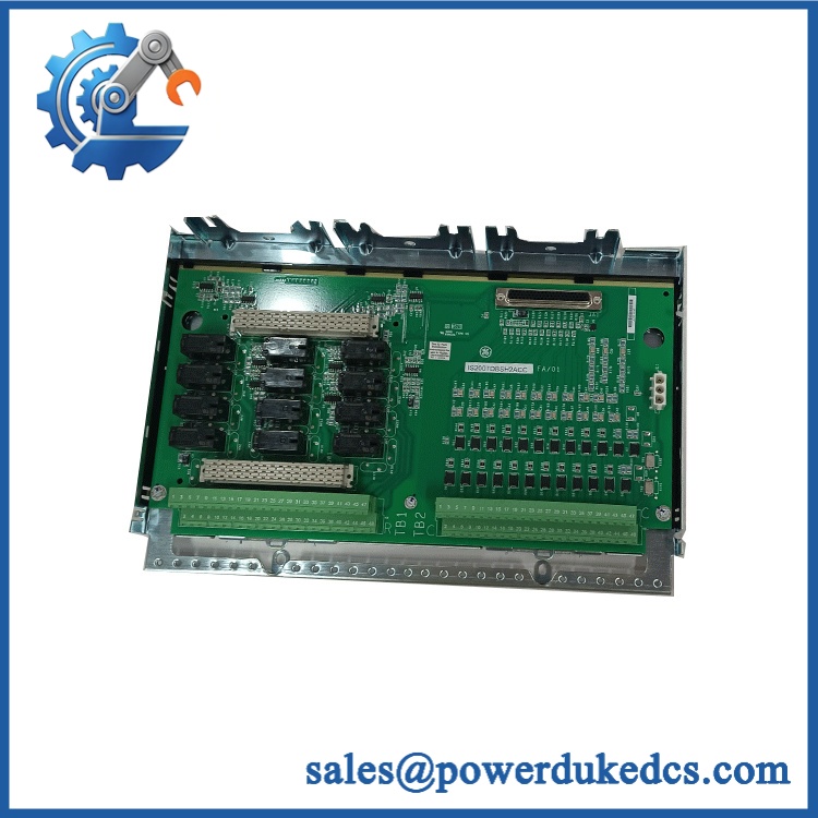
GE IS200EGPAG1BCA
Module 5: Quality Assurance & Testing SOP
- OEM anti-counterfeit visual inspection — verify GE markings, complete identification, PCB layout, component placement, connectors, labels, and traceability.
- Revision audit — record the complete board suffix and compare the hardware markings with the installed unit.
- Jumper-state documentation — photograph and record all five onboard jumper positions before energized testing or configuration changes.
- Mechanical inspection — examine mounting points, connectors, PCB edges, terminal interfaces, and heatsink areas for damage, corrosion, or deformation.
- PCB condition screening — inspect for burned components, cracked solder joints, contamination, damaged traces, capacitor leakage, and unauthorized repair.
- Electrical pre-screening — verify continuity, grounding, isolation, and abnormal resistance before applying the high-voltage control supply.
- Power-on self-test (POST) — install the board in an approved test environment and verify expected initialization and LED behavior.
- LED verification — confirm the onboard green/red indicators respond correctly to power, command, firing, and fault conditions applicable to the test setup.
- Gate-command simulation — apply controlled ESEL-equivalent firing commands and verify proper response through all applicable SCR gate channels.
- Six-channel gate-output testing — independently test each configured firing channel for correct pulse presence, timing, and isolation.
- Bridge-current feedback testing — inject controlled representative conduction-status signals and verify correct EGPA processing.
- Temperature-input testing — simulate the installed RTD or temperature-switch arrangement and verify correct diagnostic behavior.
- Airflow/fan input testing — simulate representative fan pulse or dry-contact conditions and verify the configured detection logic.
- Line-filter fuse-status testing — simulate the applicable normally closed fuse-failure contact and verify the expected status/alarm path.
- Interlock and alarm simulation — exercise representative bridge fault conditions and verify the correct downstream response.
- Extended energized run — monitor gate-command stability, diagnostic status, temperature rise, and intermittent input/output faults.
- Final QC release — photograph the exact identification and jumper configuration, retain test records, use ESD-safe packaging, and preserve complete traceability.
For this board, a basic continuity test or power-up check is not sufficient. The meaningful acceptance sequence is gate-pulse generation plus bridge-feedback and protection-input verification under controlled conditions.
Module 6: Procurement & Lifecycle FAQ
Q1. Is GE genuinely in stock, and what is the cutoff for emergency shipping?
Exact availability should be confirmed against , quantity, condition, and destination before PO release. Current industrial references show inventory claims for this exact board, but emergency fulfillment should be based on verified physical stock and the warehouse dispatch cutoff.
Q2. How do you verify the condition and authenticity of an obsolete ?
Require full part-number inspection, OEM marking verification, PCB and connector examination, electrical screening, controlled power-up, gate-pulse testing, bridge-feedback simulation, fan/airflow testing, temperature-input testing, and line-filter fault simulation. The jumper configuration and identification photographs should remain attached to the QC record.
Q3. Are there firmware compatibility issues engineers should check before issuing the PO?
The primary concerns are hardware revision, jumper configuration, ESEL interface compatibility, and bridge configuration rather than a routine firmware flash. Engineers should record the installed board revision and configuration before approving the replacement.
Q4. Can another IS200EGPA board replace ?
Not automatically. Different EGPA revisions can differ in hardware configuration and application compatibility. Match the complete number, jumper positions, connected feedback circuits, and cabinet documentation before approving a substitute.
Q5. What warranty and return terms should procurement require?
Require a written warranty period, DOA criteria, return-authorization process, serial/part-number traceability, and exclusions for incorrect wiring, improper jumper configuration, electrical overstress, or unauthorized modification. The quotation should explicitly identify , the tested condition, and the documented hardware revision.











 Start Chat


