

Description
- Model: IS200EHPAG1A
- Brand: GE
- Series: EX2100 Excitation Control
- Part Type: EHPA High-Voltage Pulse Amplifier Board
- Core Function: Amplifies low-level firing commands and provides the gate-drive interface used to control SCR devices in the excitation power bridge.
- Application: Generator excitation and power-conversion control
- System Variant: Designed for 100 mm SCR systems
- Operating Architecture: Simplex or redundant
- Transformers: 8 pulse transformers
- Transistors: 10
- Plug Connectors: 14
- Status Indicators: 1 red, 5 green, 16 amber LEDs
- Installation Location: Power Conversion Cabinet
- Power Source: Supplied through the associated EPDM power-distribution module
- Lifecycle Position: Legacy / mostly obsolete; exact replacement suitability must be verified against the installed EX2100 design.
Product Introduction
Structure B — Technical Direct
Installed in the EX2100 power conversion cabinet, the GE IS200EHPAG1A is the EHPA high-voltage pulse-amplifier board used in the excitation system. Its principal task is to interface the low-level control circuitry with the SCR power bridge by amplifying and distributing the required gate-pulse signals. Field references identify the EHPA configuration specifically with 100 mm systems, while the board can be used in simplex or redundant arrangements.
The board contains eight transformers and ten transistors, with a dense connector field carrying the pulse and monitoring circuits. Fourteen plug connectors are identified on the board, along with a 22-LED status array consisting of one red, five green, and sixteen amber indicators. Unlike the EGPA family, the EHPA version does not use the EGPA alarm and trip-level switches. (That is an important visual and functional distinction when receiving old EX2100 spare stock.)
For lifecycle planning, IS200EHPAG1A belongs to an aging EX2100 hardware population. A verified New Original or New Surplus board can therefore have significant value where the installed excitation controller still depends on the EHPA architecture, but substitution with a later revision should be based on the complete gate-drive and SCR-bridge configuration rather than the board name alone.
Core Technical Specifications
| Parameter | Value |
|---|---|
| Manufacturer | GE |
| Model | IS200EHPAG1A |
| Functional Designation | EHPA |
| Series | EX2100 Excitation Control |
| Product Type | High-Voltage Pulse Amplifier Board |
| Primary Function | SCR gate-pulse amplification and power-bridge interface |
| Supported System | 100 mm SCR system |
| Operating Architecture | Simplex or redundant |
| Pulse Transformers | 8 |
| Transistors | 10 |
| Plug Connectors | 14 |
| Connector Arrangement | 8 × 2-position, 4 × 4-position, 2 × 6-position plugs |
| Board Connectors | 3 female board connectors |
| Status LEDs | 22 total: 1 red, 5 green, 16 amber |
| Mounting Location | Power Conversion Cabinet |
| Board Power Source | Associated EPDM power-distribution module |
| Gate-Drive Function | Amplifies control pulses for SCR triggering |
| Feedback/Monitoring Role | Associated pulse/bridge status monitoring |
| Alarm/Trip Level Switches | Not provided on EHPA |
| Application Family | Generator excitation / power conversion |
| Installation Environment | excitation cabinet |
| PCB Treatment | Conformal-coated construction is reported for this board family |
| Lifecycle Position | Legacy / mostly obsolete |
The connector count, transformer count, transistor count, LED arrangement, 100 mm application, EPDM power relationship, and absence of EGPA alarm/trip-level switches are documented in secondary technical references for this exact catalog number. The actual electrical pulse amplitude and timing should not be treated as fixed catalog values without the applicable GE excitation-system documentation, because they depend on the associated architecture.
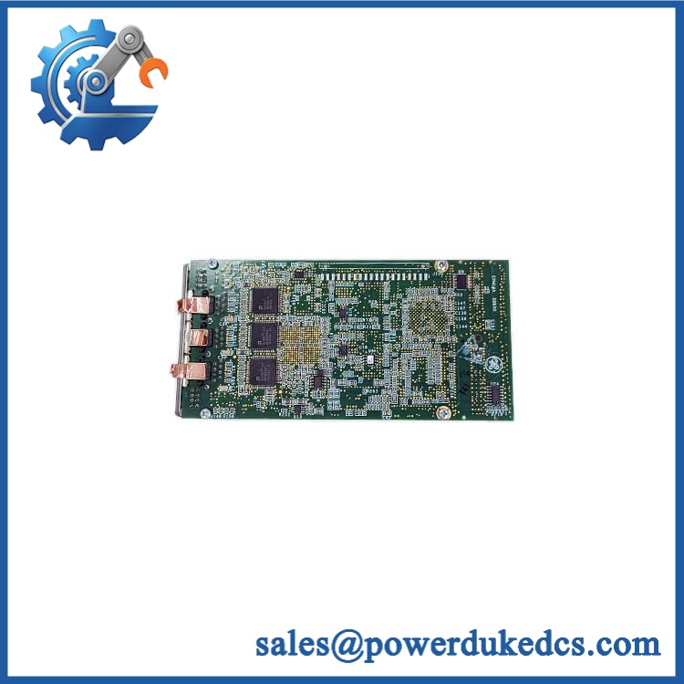
GE IS200EHPAG1A
Application Scenarios & Pain Points
The technical conclusion is straightforward: an EHPA fault can interrupt the SCR firing path and therefore affect generator excitation at the power-conversion level. Diagnosis should start with the complete excitation chain rather than replacing the board based on one alarm indication.
Generator Excitation Systems
In a large synchronous-generator application, the EHPA sits between control electronics and the SCR bridge. A gate-pulse failure can prevent the power bridge from responding correctly even when the upstream controller remains operational.
100 mm SCR Power Bridges
For a 100 mm SCR system, the board selection is architecture-specific. Using an EGPA-class board because the connector arrangement appears similar can produce a functional mismatch.
Redundant Excitation Control
With redundant controls, the board participates in a duplicated control arrangement. One failed pulse-amplifier path can generate alarms that look like a controller problem until the active and standby firing paths are compared.
Power Plant Generator Retrofits
Legacy cabinets can remain in service long after the original OEM hardware has become difficult to source. Maintaining one tested EHPA spare can reduce exposure to long outages when the excitation system is a single point of failure.
High-Temperature Power Conversion Cabinets
At 50°C+ cabinet ambient temperatures, inspect ventilation, fan operation, dust accumulation, and heat-sensitive components before concluding that intermittent pulse faults are caused only by the PCB.
🚨 Common Error Codes & Diagnostic Symptoms
Symptom/Code: No SCR gate-pulse activity at the expected bridge interface
→ Diagnosis: Possible EHPA pulse-amplifier failure, transformer degradation, connector/contact problems, upstream firing-command loss, or missing board power from the EPDM supply.
→ Action: Verify board power and the upstream gate-command path first; replace the EHPA when the failure follows the board.
Symptom/Code: Repeated gate-drive fault or abnormal bridge firing indication
→ Diagnosis: Potential pulse transformer, transistor-stage, connector, or gate-feedback issue. A fault in one amplifier path can affect the corresponding SCR firing channel.
→ Action: Compare the affected channel with a known-good channel and replace the board if the abnormal behavior remains with the EHPA.
Symptom/Code: Multiple amber/red board LEDs indicate abnormal status
→ Diagnosis: The LED pattern can point to pulse, bridge, thermal, or control-path abnormalities, but LED interpretation is configuration-specific. Do not assign a fault code solely from LED color.
→ Action: Record the complete LED pattern and compare it with the applicable GE diagnostic documentation before replacement.
🚨 Cross-Reference & Lifecycle Migration
Cross-Reference
- IS200EHPAG1A is the EHPA high-voltage pulse-amplifier board for the GE excitation system.
- The EGPA family performs a closely related gate-pulse function but is not automatically interchangeable with EHPA.
- EHPA is specifically associated with 100 mm systems in available service documentation.
- The exact SCR bridge, control topology, pulse wiring, and cabinet arrangement should be checked before approving any EGPA/EHPA substitution.
- Related EHPA revisions include later IS200EHPAG1B, IS200EHPAG1C, IS200EHPAG1D, and other family variants. A later revision should not be called a direct replacement without checking the installed system documentation.
Firmware and Configuration
The IS200EHPAG1A is primarily an analog/power-interface board rather than a modern software-configured I/O processor, so firmware flashing is not normally the central replacement issue.
The key checks are electrical and architectural:
- SCR bridge voltage/current arrangement
- Gate-pulse wiring
- EPDM power source
- Redundant versus simplex architecture
- EHPA/EGPA family compatibility
- Hardware revision
- Excitation-system configuration
A board-level replacement should therefore be accompanied by a controlled pulse-path verification rather than a firmware-only acceptance test.
Lifecycle Status
Status: Legacy / Mostly Obsolete
Secondary lifecycle references characterize the as largely obsolete, which changes the stocking strategy considerably. Where the installed excitation cabinet still depends on this exact hardware, maintain a tested spare and preserve the associated system documentation.
A migration plan should address the full excitation architecture, not simply the EHPA card. Power bridge components, gate wiring, cooling, feedback circuits, and controller hardware may all be involved.
Field Engineer’s Tech Notes
Warning 1 — Do not confuse EHPA with EGPA.
The two boards share a gate-pulse role, but the EHPA is identified with 100 mm systems, and the available documentation specifically notes that EHPA does not have the alarm and trip-level switches found on EGPA. Verify the system type before installation.
Warning 2 — Treat the connectors as mechanically fragile.
The board has a large number of multi-position plugs, and field references specifically warn that the connector/terminal metallic surfaces can be damaged during installation. Never force a plug into place or use the connector body to pull a board into alignment.
Before removing the old board, photograph every cable location. With fourteen plug connectors, one misplaced connection can create a troubleshooting session far longer than the original board replacement.
Strict QA & Testing SOP
Step 1 — Inbound Identity Verification
Record:
- GE
- EHPA designation
- Serial number
- Hardware revision
- Any secondary board identifiers
- Intended cabinet/system
Photograph the complete nameplate and connector field.
Step 2 — Mechanical Inspection
Inspect all fourteen plug connectors and the three board connectors for:
- Bent contacts
- Cracked housings
- Damaged locking features
- Oxidation
- Contamination
- Discoloration
- Moisture evidence
Inspect the eight transformers and visible power components for mechanical or thermal damage.
Step 3 — Power-Source Verification
Confirm the compatible EPDM power-distribution arrangement before applying power. Measure the applicable supply under a controlled test condition and record startup behavior.
Step 4 — Visual LED Test
Power the board in an approved test fixture and verify expected operation of:
- 1 red LED
- 5 green LEDs
- 16 amber LEDs
The LED pattern should be compared with the relevant GE diagnostic documentation, not simply judged by whether the lamps illuminate.
Step 5 — Pulse-Amplifier Functional Test
Using a purpose-built -compatible test fixture:
- Apply a controlled input firing command.
- Verify corresponding amplifier response.
- Confirm pulse transformer operation.
- Check representative output channels.
- Compare channel-to-channel behavior.
- Check for abnormal waveform distortion or missing pulses.
Actual gate-drive voltage and pulse timing must be tested against the applicable GE system specification.
Step 6 — Redundancy Verification
Where the test system supports redundant operation, exercise the appropriate primary/standby path and verify that the EHPA responds correctly in the intended architecture.
Step 7 — Connector and Intermittency Test
Perform controlled connector manipulation and vibration screening where appropriate to identify intermittent contacts. Do not apply excessive force to the plug interfaces.
Step 8 — Thermal Observation
Run the board for an extended period under representative conditions and monitor transformer, transistor, and power-component temperature behavior.
Step 9 — Final QC Documentation
Record:
- Exact part number
- Serial number
- Hardware revision
- Input test results
- Pulse-output results
- LED status
- Power test
- Thermal observation
- Redundancy test where applicable
- Test date
- Technician sign-off
Step 10 — ESD and Shock Protection
After testing, place the board in an ESD-safe antistatic package with connector protection and adequate mechanical cushioning. Store it in a clean, dry location away from condensation and corrosive contamination.
Test videos are available when visual evidence is included with the individual inspection package.
Buyer’s FAQ
A: No assumption should be made here. This board participates directly in an excitation power-conversion gate-drive path. Replacement should be performed with the excitation system in the approved safe state, with stored-energy hazards controlled and the site’s GE maintenance procedure followed.
Q: Is the same as an EGPA board?
A: No. They have related gate-pulse functions, but EHPA is identified with the 100 mm system, and the board does not have the EGPA alarm and trip-level switches. Confirm the installed excitation architecture before ordering a substitute.
Q: How can I verify a New Original board?
A: Check the GE nameplate, complete catalog number, serial number, board revision, connector arrangement, transformer population, LED layout, and traceability records. A clean PCB is not sufficient evidence of original condition.
Q: What warranty should I require?
A: State the warranty period and supplied condition explicitly. For an EHPA board, acceptance should cover the actual failure mechanisms that matter: controlled power-up, LED behavior, pulse amplification, representative gate-pulse channels, connector integrity, and extended-run stability.











 Start Chat


