

Description
- Brand: GE
- Full Model Number: IS200EPSMG1AEC
- Lifecycle Status: Legacy / Obsolete
- Core Function: EX2100 excitation-system power supply board
- Top 3 Technical Specs: 125 VDC input; 5 VDC, 15 VDC, 24 VDC and 70 VDC outputs; Front-panel LED status indication
- Stock & Condition: Physical stock verification required; New Surplus / Tested Refurbished; Emergency dispatch subject to QA release
Module 3: Obsolescence & Supply Chain Deep Dive
A failed GE IS200EPSMG1AEC can interrupt the internal power distribution of an EX2100 excitation system even when the controller, interface boards, and power bridge remain serviceable. Available technical records identify the EPSM as an EX2100 power supply board, with the IS200EPSMG1AEC configuration accepting 125 VDC and generating multiple internal supply rails. Reported outputs include 5 VDC, 15 VDC, 24 VDC, and isolated 70 VDC for contact wetting, while front-panel LEDs provide operating-status indications. The board is associated with the GE Mark VI/EX2100 platform.
For a plant maintaining an installed EX2100 system, replacing the failed EPSM board can cost materially less than redesigning the excitation-system power architecture. Existing EPDM input hardware, controller assemblies, terminal boards, field wiring, and application configuration can remain in service when the exact board revision is restored. That reduces engineering labor, panel modifications, commissioning effort, and outage exposure. —The critical procurement point is the 125 VDC input and output-rail configuration: supplier records consistently identify this board as a power-supply assembly, but published third-party specifications are not fully consistent, so the physical nameplate and applicable GE drawing should take precedence over generic catalog data.
Module 4: Compatibility & Replacement Matrix
| Replacement Scenario | Classification | Engineering / Procurement Guidance |
|---|---|---|
Exact IS200EPSMG1AEC replacing the same installed board |
Drop-in Replacement — subject to verification | Match complete part number, hardware revision, EPDM input, connectors, and cabinet location |
| Same EPSM family with an approved compatible revision | Software Compatible / Hardware Verification Required | Confirm voltage rails, connector pinout, and system configuration |
IS200EPSMG1AED or another EPSM suffix replacing IS200EPSMG1AEC |
Engineering Review Required | Confirm exact revision, electrical characteristics, and EX2100 application |
| Different GE excitation-system power board | Hardware Modification | Requires power-rail, connector, mounting, and system-engineering review |
Estimated switch cost/time: For a tested replacement already staged on-site, plan approximately 2–5 hours for controlled isolation, board replacement, connector verification, power-rail checks, and system functional testing. A newly sourced unit may add 1–5 business days for inspection and expedited transport. These are planning estimates.
Field Traps — Watch Out
- 125 VDC input verification: Available technical records identify the IS200EPSMG1AEC as accepting 125 VDC from the associated EPDM assembly. Do not substitute a board based on unrelated AC-input specifications found in generic listings.
- Output-rail matching: Reported EPSM outputs include 5 VDC, 15 VDC, 24 VDC, and isolated 70 VDC. Verify the installed cabinet’s required rails before approving an alternate EPSM revision.
- Revision sensitivity: The EPSM family includes different suffixes, including
andIS200EPSMG1AED. Do not approve another suffix solely because the baseIS200EPSMG1Aidentifier matches. - Connector and backplane location: Confirm every connector and the intended EPBP/backplane position before energization. A mechanically similar board may still have a different electrical interface.
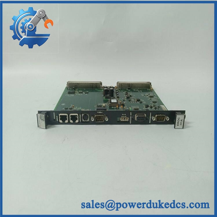
GE IS200EPSMG1AEC
Module 5: Quality Assurance & Testing SOP
The should be qualified as a DC-input power-conversion assembly. A visual inspection and simple resistance check are not sufficient for release.
- Part-number verification: Confirm
, revision, serial/traceability information, and GE identification markings. - OEM anti-counterfeit visual inspection: Inspect GE labels, PCB identifiers, component layout, connector construction, transformer/inductor assemblies, and evidence of unauthorized rework.
- Physical condition inspection: Check the PCB, capacitors, transformers, inductors, fuses, transistors, connectors, and mounting points for cracks, corrosion, contamination, or thermal damage.
- Connector inspection: Examine all board connectors for bent contacts, oxidation, contamination, damaged housings, or poor mechanical retention.
- Fuse/protection check: Inspect accessible fuses and protection components for damage and verify continuity where the approved test procedure permits.
- Continuity testing: Verify applicable input, output, ground, and protective paths before controlled energization.
- Insulation resistance test: Check applicable input-to-ground and output-to-ground insulation using the approved test voltage and acceptance criteria.
- Power-on self-test (POST): Install the board in the appropriate test assembly and verify startup behavior and front-panel LED indications.
- Input-voltage verification: Apply a controlled 125 VDC input and record input current and startup behavior.
- Output-rail verification: Measure the applicable 5 VDC, 15 VDC, 24 VDC, and 70 VDC outputs and compare them with the approved GE test limits.
- 70 VDC contact-wetting test: Where applicable, verify the isolated 70 VDC supply used for contact-wetting functions.
- Voltage-regulation test: Monitor output stability under no-load and representative-load conditions.
- Load testing: Apply representative loads independently to the supported supply rails while monitoring voltage deviation and thermal behavior.
- Overcurrent protection test: Where the test fixture permits, apply controlled overload conditions and confirm the expected protective response.
- LED status verification: Confirm each front-panel indicator displays the expected power and operating status.
- Ripple/noise check: Measure representative DC output ripple and noise under load to detect failing capacitors or switching-stage problems.
- Thermal observation: Monitor transformer, switching components, capacitors, and heat-generating areas during sustained operation.
- Backplane/interface test: Verify stable electrical connection between the EPSM and the applicable backplane assembly.
- Extended observation: Operate the board under representative load conditions to identify intermittent startup, voltage drift, thermal faults, or LED anomalies.
- Final QC release: Record full part number, revision, input voltage, each measured output rail, load-test results, photographs, condition grade, test date, and QC authorization.
Available supplier data reports a 125 VDC input and multiple DC output rails for this specific configuration, while other online records provide inconsistent dimensions and electrical claims. For procurement and receiving inspection, the board nameplate and approved GE documentation should therefore be treated as the controlling technical reference.
Module 6: Procurement & Lifecycle FAQ
Q1. Is the GE genuinely in stock, and what is the cutoff for emergency shipping?
Physical inventory should be verified against the exact marking and revision before the PO is accepted. Current supplier records show inventory claims, but actual physical availability, condition, and QA status should be confirmed before making an emergency-shipping commitment.
Q2. How do you guarantee the condition and authenticity of an obsolete ?
Require exact part-number verification, OEM visual inspection, PCB and connector examination, fuse checks, controlled 125 VDC power-up, output-rail measurement, representative-load testing, thermal observation, and a documented QC record. Photographs of the actual board and identification markings should remain with the procurement file.
Q3. Are there firmware compatibility issues engineers should check before issuing the PO?
The EPSM is primarily a power-conversion board, so firmware is not the main compatibility concern. Engineers should instead verify the exact hardware revision, EPDM input arrangement, connector pinout, required DC output rails, backplane location, and associated controller configuration before installation.
Q4. Can another IS200EPSMG1A-series board replace ?
Not automatically. Suffixes such as AEC and AED should be treated as configuration identifiers until the applicable GE documentation confirms interchangeability. Match the complete ordering number, input requirements, output rails, connectors, and revision before approving substitution.
Q5. What warranty and return terms should be written into the PO?
Specify warranty duration, DOA coverage, input-power performance, output-rail conformity, load-test performance, thermal behavior, return authorization, inspection period, and serial-number traceability. For refurbished inventory, require the actual DC power-supply test report and define whether failures discovered during commissioning are covered.











 Start Chat


