

Description
- Brand: GE General Electric
- Full Model Number: IS200JPDMG1ACC / S1AT005
- System/Series Family: Mark VI Turbine Control
- One-Sentence Core Function: JPDM power-distribution board providing individually protected control power to connected Mark VI I/O packs
- Top 3 Hardcore Specs: 28 VDC distributed control power; 35 A maximum current capability reported for the board; J1 and J1X daisy-chain interfaces
- Stock Status: New Surplus / Fully Tested Refurbished — exact board revision and S1AT005 identification verified before shipment
Module 3: Commercial-Technical Deep Dive
A JPDM failure can remove power from multiple I/O packs while the Mark VI controller itself remains operational. The GE IS200JPDMG1ACC is identified as a Mark VI power distribution card, with technical references describing protected power distribution to individual I/O packs through fused output branches. The board uses J1 and J1X for daisy-chaining, allowing multiple distribution cards to participate in a larger control-power architecture. GE-oriented technical references also describe three separate power buses with jumper options for configuring the distribution arrangement.
The important electrical distinction is that some published listings describe the external Mark VI source as a 125 VDC battery system, while the JPDM board itself is described in other technical references as accepting 28 VDC for distribution to downstream I/O hardware. Those are not interchangeable specifications. The safe procurement interpretation is that the Mark VI cabinet may derive its control power from a higher-voltage source through an appropriate converter, while the JPDM operates on the downstream 28 VDC distribution bus. The board is also reported with a maximum current capability of approximately 35 A, but branch limits and upstream connector ratings must be checked against the actual cabinet design before loading the card to that level.
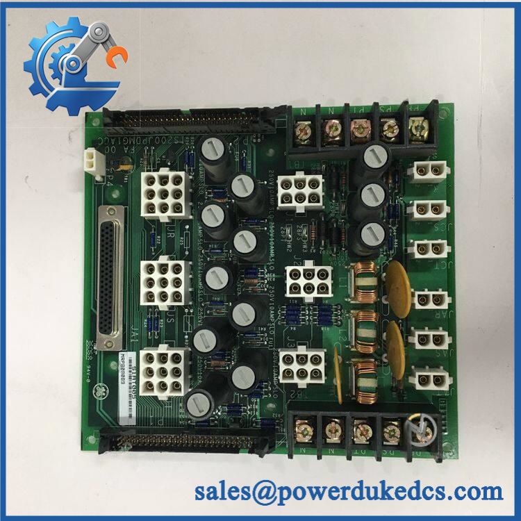
GE IS200JPDMG1ACC
Module 4: Compatibility & Installation Traps
Migration/Compatibility
- Replacement status: Configuration-specific Mark VI power-distribution board.
- Functional identity: JPDM Power Distribution Card used to distribute protected control power to I/O packs.
- System family: GE Mark VI turbine-control architecture.
- Firmware requirement: None for the passive power-distribution function itself. Associated I/O packs and controllers retain their own firmware.
- Logic rewrite: Not applicable to the power board itself. Downstream I/O power status and cabinet operation should be verified after replacement.
- Daisy-chain architecture: J1 and J1X allow multiple JPDM boards to be interconnected. The first board in the chain can therefore impose an upstream current constraint on downstream cards.
⚠️ Field Traps (Watch Out)
- Source-voltage confusion: Do not label the board simply as a “125 VDC input card.” Technical references distinguish the Mark VI cabinet power source from the JPDM’s 28 VDC distribution input. Verify the actual cabinet schematic before energization.
- Daisy-chain current limit: When several JPDM boards are linked through J1/J1X, the upstream connector and first-board path can become the limiting factor. The total downstream load must remain within the specified upstream rating.
Fuse identification: Individual output branches are protected. Verify every fuse position and rating before reconnecting an I/O pack; a wrong fuse value can defeat the intended branch protection. - Jumper configuration: The board can use jumpers to configure its three power buses for different supply arrangements. Photograph every jumper position before removing the existing board.
- Hazardous-location wiring: Some references identify the board for use in hazardous locations when installed according to the applicable GE and UL/ATEX requirements. The certification applies to the complete installation, not the bare PCB in isolation.
- ESD and LOTO: Isolate the control-power source and use grounded ESD procedures before handling the card or its field wiring.
Module 5: Quality Assurance SOP
Our pre-shipment inspection for a GE IS200JPDMG1ACC S1AT005 focuses on power-distribution integrity, branch protection, and exact hardware identification:
- OEM anti-counterfeit visual inspection — verify GE markings, IS200JPDMG1ACC identifier, S1AT005 marking, PCB artwork, revision data, terminal blocks, connectors, and manufacturing labels.
- Part-number capture — photograph the front, rear, labels, connectors, fuse positions, and jumper settings.
- Revision verification — compare the supplied ACC revision against the customer’s removed board and cabinet documentation.
- PCB condition inspection — inspect solder joints, connectors, fuses, varistors, terminal points, contamination, corrosion, and evidence of overheating.
- Jumper/configuration record — document all installed jumper positions before power application.
- Fuse verification — inspect each branch fuse and confirm the rating against the applicable GE configuration documentation.
- Power-input verification — apply the documented 28 VDC distribution supply under controlled laboratory conditions; monitor startup current and abnormal heating.
- Power-on self-test (POST) — verify expected board status and stable power distribution with no abnormal current draw.
- Branch-output testing — test representative protected output channels under controlled loads and confirm correct output voltage.
- Protection verification — where the approved test fixture allows, verify branch protection behavior without exceeding manufacturer limits.
- J1/J1X continuity and daisy-chain verification — confirm correct connectivity and isolation between upstream and downstream distribution paths.
- Multi-bus verification — where applicable, test the configured bus arrangement and verify correct output distribution.
- Loaded endurance test — operate the board under representative load while monitoring voltage stability, current, temperature rise, and fuse behavior.
- Configuration record — document part number, revision, S1AT005 marking, jumper positions, fuse ratings, input voltage, branch measurements, and photographs.
- Final QC review — compare every recorded identifier with the customer’s exact replacement requirement.
- ESD packaging — protect the PCB, connectors, and fuse section against ESD, impact, dust, and moisture before shipment.
The strongest published technical references agree on the core function, J1/J1X daisy-chain architecture, protected branch outputs, and Mark VI application. They differ on how the upstream 125 VDC cabinet source relates to the board-level 28 VDC input, so the final test procedure should follow the actual cabinet schematic rather than a generic reseller specification.
Module 6: CRO-Driven Buyer FAQ
1. Is GE IS200JPDMG1ACC obsolete, and how do I verify authenticity?
The IS200JPDMG1ACC is a legacy GE Mark VI power-distribution board. Verify the complete board number, ACC revision, S1AT005 identification, PCB layout, jumper arrangement, fuse population, and connector configuration before accepting a replacement.
2. Does take 125 VDC or 28 VDC?
The published references need to be interpreted carefully. The Mark VI control system is commonly supplied from a 125 VDC battery source, while technical descriptions of the JPDM itself identify 28 VDC as the board-level distribution input. The cabinet power-conversion arrangement determines how those two levels relate. Confirm the actual terminal voltage from the installed GE schematic before energization.
3. What does the JPDM board power?
The board distributes protected control power to connected I/O packs and associated Mark VI control hardware. Its output branches are individually protected, allowing a fault on one branch to be isolated from other downstream circuits.
4. Can be hot-swapped?
Do not assume live replacement is permitted. The board carries control-power distribution and may be connected to multiple energized I/O packs through the J1/J1X daisy-chain. Isolate the applicable power source, verify zero-energy conditions, and follow the GE Mark VI maintenance and site LOTO procedure before removal.
5. What warranty and technical support should I expect?
Warranty duration should be stated on the quotation for the exact physical board supplied. Technical support should cover part-number and revision matching, jumper/fuse identification, power-source verification, J1/J1X wiring checks, branch-output testing, and documented pre-shipment QA results. It should not substitute for turbine-control engineering, hazardous-location certification, or site commissioning.











 Start Chat


